Addy
100 W
Hex-Cell-Holder
A parametric OpenSCAD project to generate STLs models of hexagonal lithium cell holders, boxes, and caps to be 3d printed.
![giphy[1].gif](https://endless-sphere.com/sphere/data/attachments/131/131921-8b49001ae0167bc115cef8a04d0a0890.jpg "giphy[1].gif")
View attachment 3
![ffPChFY[1].jpg](https://endless-sphere.com/sphere/data/attachments/131/131922-6628242df436cbce924ebf71327f0718.jpg "ffPChFY[1].jpg")


How does it work?
Hex-Cell-Holder uses OpenSCAD to create solid 3D CAD objects. Openscad allows easy parametric configuration of a 3d model which means you don't need to be a coder to create a specific model that you need.
http://www.openscad.org/
Who should use this?
This project was primarily created to make lithium ion packs out of 18650 for ebikes with the help of a 3d printer. You can make any size pack you want out of any size lithium cell.
Configuration
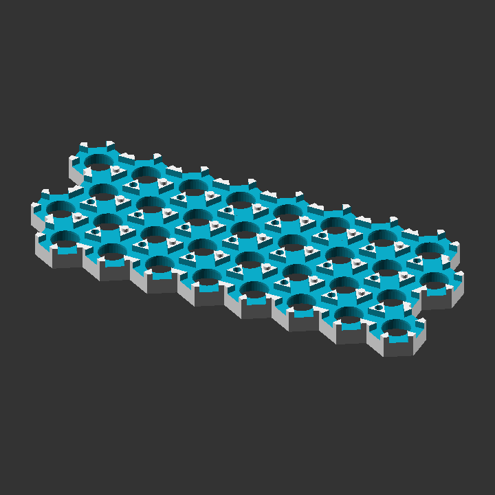
Holders
You can generate a holder of any number of rows, columns, rectangular or parallelogram, and strip or bus. Below is an example configuration.
The holders use small tabs to keep the cells in. If you happen to have a faulty cell in a completed pack, you can cut the tabs to remove the cell and easily replace it.
Check the console for extra information like whether or not you need a mirrored holder or total widths or lengths.
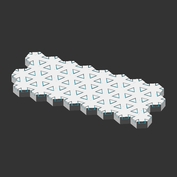
Caps
Caps can be generated to fit over the holders for when you don't need a full box to house the pack but still want the terminals safely covered.
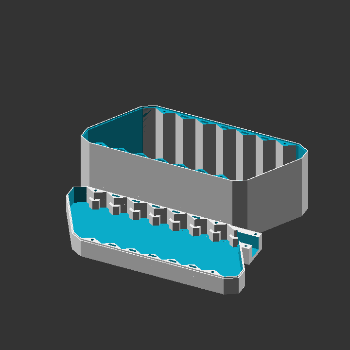
Boxes and wire clamp
Your battery pack can be put into a box to be fully enclosed and protected. There is also a wire clamp for your bulk leads to provide some strain relief. The box has many options so read through the config to see what you can do
Fit test
fit_test.scad generates holders to test fit which cell_dia to use for the holders.
Bat scripts to generate stls
Bat files are added to quickly generate multiple stls. This saves a lot of time by not having to change part_type and part, rendering, and then exporting as an stl for each piece.
Download
The latest version of this project can be downloaded from the github repository:
https://github.com/Addy771/Hex-Cell-Holder
You can also get it at Thingiverse:
https://www.thingiverse.com/thing:3029966
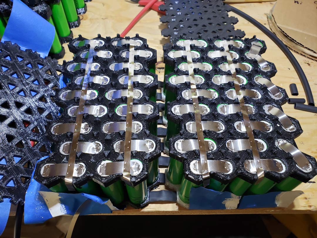
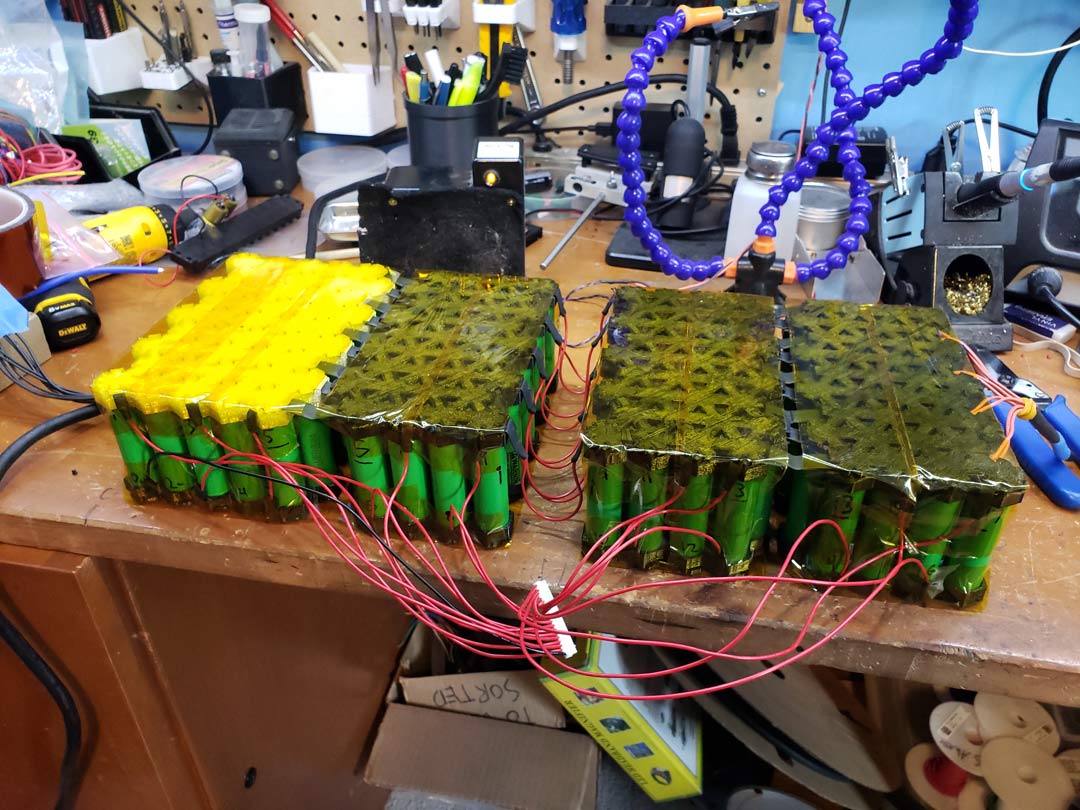
This project began in 2017, in a discussion here on ES. Since then, my partner Albert and I have been improving the OpenSCAD scripts and adding new features. We've found this project to be very useful in our own battery builds and I think it could be useful for the ES community. If you use these cell holders I would love to see pictures of your battery builds!
A parametric OpenSCAD project to generate STLs models of hexagonal lithium cell holders, boxes, and caps to be 3d printed.
View attachment 3
How does it work?
Hex-Cell-Holder uses OpenSCAD to create solid 3D CAD objects. Openscad allows easy parametric configuration of a 3d model which means you don't need to be a coder to create a specific model that you need.
http://www.openscad.org/
Who should use this?
This project was primarily created to make lithium ion packs out of 18650 for ebikes with the help of a 3d printer. You can make any size pack you want out of any size lithium cell.
Configuration
Holders
You can generate a holder of any number of rows, columns, rectangular or parallelogram, and strip or bus. Below is an example configuration.
The holders use small tabs to keep the cells in. If you happen to have a faulty cell in a completed pack, you can cut the tabs to remove the cell and easily replace it.
Check the console for extra information like whether or not you need a mirrored holder or total widths or lengths.
Code:
cell_dia = 18.4;    // Cell diameter default = 18.4 for 18650s **PRINT OUT TEST FIT PIECE STL FIRST**
cell_height = 65;	// Cell height default = 65 for 18650s
wall = 1.2;         // Wall thickness around a single cell. Make as a multiple of the nozzle diameter. Spacing between cells is twice this amount. default = 1.2

num_rows = 3;
num_cols = 5;

holder_height = 15; // Total height of cell holder default = 15
slot_height = 3.5;  // Height of all slots default = 3.5 mm is a good size for 14 awg solid in slots


col_slot_width = 4; // Width of slots between rows default = 6
row_slot_width = 8; // Width of slots along rows default = 6

pack_style = "rect";	// "rect" for rectangular pack, "para" for parallelogram

wire_style = "bus";		// "strip" to make space to run nickel strips between cells.
                      // "bus" to make space for bus wires between rows
part_type = "normal";   // "normal","mirrored", or "both". "assembled" is used for debugging.  You'll want a mirrored piece if the tops and bottom are different ( ie. When there are even rows in rectangular style or any # of rows in parallelogram. The Console will tell you if you need a mirrored piece).

part = "holder";   		// "holder" to generate cell holders,
Caps
Caps can be generated to fit over the holders for when you don't need a full box to house the pack but still want the terminals safely covered.
Code:
part = "cap";   		// "holder" to generate cell holders,
                // "cap" to generate pack end caps,
                // "box lid" to generate box lid
                // "box bottom" for box bottom
                // "wire clamp" for strain relief clamp

                // Note: There are no boxes for parallelogram packs.


cap_wall = 1.2;				  // Cap wall thickness (default = 1.2 recommend to make a multiple of nozzle dia)
cap_clearance = 0.4;		// Clearance between holder and caps default = 0.2
Boxes and wire clamp
Your battery pack can be put into a box to be fully enclosed and protected. There is also a wire clamp for your bulk leads to provide some strain relief. The box has many options so read through the config to see what you can do
Code:
part = "box lid";   		// "holder" to generate cell holders,
                // "cap" to generate pack end caps,
                // "box lid" to generate box lid
                // "box bottom" for box bottom
                // "wire clamp" for strain relief clamp

                // Note: There are no boxes for parallelogram packs.

box_wall = 2.0;				// Box wall thickness (default = 2.0 recommend to make at least 4 * multiple of nozzle dia)
box_clearance = 0.4;		// Clearance between holder and box default = 0.2


// Box clearances for wires
bms_clearance = 8; 			// Vertical space for the battery management system (bms) on top of holders, set to 0 for no extra space
box_bottom_clearance = 0;	// Vertical space for wires on bottom of box
box_wire_side_clearance = 3; // Horizontal space from right side (side with wire hole opening) to the box wall for wires
box_nonwire_side_clearance = 0; // Horizontal space from left side (opposite of wire hole) to the box wall for wires

wire_diameter = 2;			// Diameter of 1 power wire used in the strain relief clamps default = 5 for 10 awg stranded silicon wire
wire_clamp_bolt_dia = 3;	// Bolt dia used for clamping wire default = 3 for M3 bolt
clamp_factor = 0.7;			// Factor of wire diameter to be clamped. Higher number is less clamping force (default=0.7 max=1.0)
bolt_dia = 3;				// Actual dia of bolt default = 3 for M3 bolt
bolt_head_dia = 6;			// Actual dia of bolt head default = 6 for M3 socket head bolt
bolt_head_thickness = 3;	// Thickness (height) of bolt head default = 3 for M3 Socket head
ziptie_width = 8;
ziptie_thickness = 2.5;
Fit test
fit_test.scad generates holders to test fit which cell_dia to use for the holders.
Code:
size_list = [18.0,18.2,18.4,18.6]; // Add size to test in this array.

wall_thickness = 1.6;
cell_depth = 10;
Bat scripts to generate stls
Bat files are added to quickly generate multiple stls. This saves a lot of time by not having to change part_type and part, rendering, and then exporting as an stl for each piece.
Download
The latest version of this project can be downloaded from the github repository:
https://github.com/Addy771/Hex-Cell-Holder
You can also get it at Thingiverse:
https://www.thingiverse.com/thing:3029966
This project began in 2017, in a discussion here on ES. Since then, my partner Albert and I have been improving the OpenSCAD scripts and adding new features. We've found this project to be very useful in our own battery builds and I think it could be useful for the ES community. If you use these cell holders I would love to see pictures of your battery builds!