Hummina Shadeeba said:
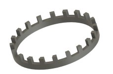
The paper describes using just a steel ring not this teethed thing I posted which is common in cylindrical motors to space the magnets which is so similar yet always done in aluminum.
right, I could certainly test the ring idea. but again, I wonder how much weight savings is really attainable. but I'm willing to try for science if nothing else
Hummina Shadeeba said:
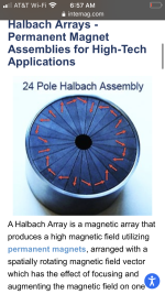
Wonder how effective your quasi hallbach is and how small the pole would need to be to have a true hallbach and like 99% of the field trapped. I had a list of all the hallbach variations but dont know where it went but it needed like 4/5 of the magnets being used as sideways magnets to reach its full potential. Maybe hallbach would be best suited with a unique stator with thin teeth and signing up with emetor again and figure stuff out instead of many vague unknowns and remember it would model hallbach arrays.)
I have seen variations of halbachs as well. but it seems you incur more weight in magnets that you would otherwise just using steel. once you need 4 magnets for a single pole, it seems like its not worth it, also, this limits the pole width, based on the size of the magnets you can get, and if you are looking for segmented arc magnets like in the image you provided, they can get pricey really quick, and tolerances are more important.
The concept of mine was to keep it relatively cheap. I was able to buy 1000 of each type of magnet for like $300 USD. This gives me enough to make ~20 motors with the current pole count.
Earlier in the thread I posted about my findings with the simulations that I was running, and on the outer diameter, the spacing of my magnets did leak some out of the back, but adding 1.5mm of steel was all that was needed to prevent leakage.
Also I made a graph that shows permutations of iron thickness vs halbach/no halbach using the same bar magnets. I found that you could get the highest flux density using a combination of iron and halbach.
Granted if not using halbach, you could fit more poles, but this also means each phase needs to be packed together tighter. So I feel as though there is an optimization to be had in the balance of all these factors, and I think that what I have now is fairly optimized.
Hummina Shadeeba said:
(Id skipped to the end of your thread abs just now read most.. why use litz wire? I thought it’s value is in avoiding skin effect at very high frequency. Or maybe that’s the wire you have so that’s what you use.)
Your understanding is the same as mine, its to prevent skin effect at high frequencies. but it also provides flexibility when working with it. Its definitely not something that I had and decided to use, I actually spend a lot of time making it from one large spool of 32 gauge stuff. I would really like to see a chart or find some details about where litz is applicable. I assumed with a high pole count I would be dealing with higher frequency, but perhaps its really not that high (Keep in mind. I have no formal mechanical or electrical engineering education, and really had no clue what I was doing when I started this project, and litz wire was a design decision that I made early on and just never strayed away from) I have recently been thinking about using something with a larger gauge so I can play with higher current, and likely less strands to keep the equivalent gauge the same.