First Electric Motorcycle Conversion Advice (1974 Honda CB360)

As for precharge, breaker and all that stuff, I suggest not bothering yourself with it.

It only will add more weight, more complexity and more failure points, for no added value. A smart BMS will do all of that already, because a BMS is basically a breaker (it monitors current and you can tell it to cut power if it goes over any level of your choice) and a contactor (the BMS can cut off the power completely either with a long press on a physical button, or in the phone app by clicking on a button), and smart BMSs include a precharge system which even allows you to set and change the precharge current to whatever value you want in just a few clicks in the app.
Also if something is damaged the BMS can detect it and it will cut power/beep at you.

So there's really no need to double down on this. In my opinion the only thing you should really add to a BMS is a good fuse between the BMS and the battery. In case the BMS goes wrong the fuse will be there to cut the power and it'll protect the battery from damage.
All that contactor/precharge/breaker stuff made sense a long time ago, but theyre completely outdated now that we got decent and cheap smart BMS.
Hm, I might have to disagree with you on a few points. I don't think any of your points are inherently wrong: it's true that most BMSs are able to protect against overcurrent, turn on/off. But some of them do that with different levels of difficulty and/or interfaces. For example, I know that your ANT BMS does have a physical on/off button. But JKBMS doesn't, you can only access that function via an app. Others may not have a button either. And BMS with a precharge? That's actually cool, I haven't seen or heard of that before, I'll have to keep my eye out. But again, that means not all BMSs have that function.

If/when they do have all the above functions, most of the time their interface is mainly via an app. Some people prefer not to have to use their phone for everything, and like to have physical and analog interfaces (I just started a whole different thread about how I'd rather teach myself how to mod a physical analog voltmeter for my desired range, rather than rely on an LCD screen with a simulated dial gauge). It's not always about distrust of programming or computers. When I need to go work on some of the cabling on my bike, or pull off covers and expose cables for service reasons, I'd rather have a physical switch that I can turn off, and can see with my eyes that it's in the off position, than to just trust that I remembered to turn it off with my phone. I do both, for the record.

While it's unlikely for a BMS to have a serious failure, when the FET's fail, they can fail closed and are then unable to shutoff current. It's exceedingly unlikely for a contactor to fail closed, there's a spring pushing it towards open position. I suppose the only way for it to fail closed would be for the contacts to weld together. Which is why I recommended a contactor way way overrated for OP's use, at 900vdc and 500A capability, for his 72v/200A capable system. In addition, depending on exactly what parts were used to build a BMS, turning off output voltage may still cause some voltage to leak through. I'm not an electrical engineer, I just know that when I turn off my BMS via an app, I can still get low voltage readings off my battery terminals. I'd rather see 0V.

I can't argue against your point that more elements = more failure points. But perhaps that's can be a good thing? If something is wrong with a system that causes one of you 4-5 elements between your battery and controller to fail, I'd rather catch that failure point and fix whatever the issue was, and only have broken one small element, rather than the BMS, if the BMS is your only protection (though of course you did recommend a hard fuse). It's true that there are more, cheaper BMSs available now, but "cheap" is relative, as a good BMS can be $100-300 USD, and I'd want several elements protecting that investment and helping it out. Especially since the contactor I suggested is $15, the breaker can be found for $10 or less, and a resistor for precharge could cost $0.25, if that.

As for added weight? The contactor is 450g, the breaker is 150g, a resistor is a couple grams, and we'll assume 250g for the extra copper lugs that you'll need to connect them. If someone is concerned about saving 750g on their build, you could just skip breakfast or leave your water bottle at home.

Again, I don't think you're wrong with skipping contactor/precharge/breaker. Just making sure OP is informed.
 
And BMS with a precharge? That's actually cool, I haven't seen or heard of that before
Yes, the Ant BMS does that, you can set whatever precharge current you want.
I can't speak for every BMS brands, indeed some are better than others. But the ANT is doing everything I mentionned.

If/when they do have all the above functions, most of the time their interface is mainly via an app.
Well yeah, but there is no possible adjustment on a physical breaker. If you want to change the breaker switching current value then... well you have to purchase a new one. If you want to change the overcurrent time delay? well same, you just can't.
Same thing for precharge current, you'll have to install another resistor with a different value.
And with a physical contactor you need to energize a coil constantly, which is inefficent because it draws power for no good reason. Sure its not a lot, but I rather use my battery for moving the bike rather than heating a coil.

So yeah, you need an app to change the parameters... but at least you can change them, which is not possible otherwise anyway.

Some people prefer not to have to use their phone for everything, and like to have physical and analog interfaces (I just started a whole different thread about how I'd rather teach myself how to mod a physical analog voltmeter for my desired range, rather than rely on an LCD screen with a simulated dial gauge)
There is a voltage indicator clearly visible on the BMS screen, so you can either rely on the gauge or on the actual voltage value, whatever you prefer. Here again, at least you have a choice.
Also, the coulomb meter is entirely configurable, so you can dial in the range to get it very accurate if you want to. A lot more accurate than watching the voltage.

. It's not always about distrust of programming or computers. When I need to go work on some of the cabling on my bike, or pull off covers and expose cables for service reasons, I'd rather have a physical switch that I can turn off, and can see with my eyes that it's in the off position, than to just trust that I remembered to turn it off with my phone. I do both, for the record.
Well that's exactly what the ANT BMS does. You press the off button for 6 seconds, and it switches off the current for the whole bike. You can see it easily just by doing that with the lights switched ON before turning off the BMS in case you don't trust it. That's how I do it every time. If the current comes back for whatever reason then you'll see the lights switching on immediately.
Simple.

While it's unlikely for a BMS to have a serious failure, when the FET's fail, they can fail closed and are then unable to shutoff current. It's exceedingly unlikely for a contactor to fail closed,
That's what I've always heard as well.
Then a friend of mine did the experiment himself, tried some automotive contactors. They all failed closed. It was a bitter disappointment as he wanted to install one to bypass the BMS mosfets in order to go over 600A battery.
BYD stuff, some big and beefy contactors intended for EVs, not the cheap stuff.

So I have to disagree on that now, even though I thought it was correct just a few years ago.
Also, that is why I insist on having a good fuse at the battery.

a BMS, turning off output voltage may still cause some voltage to leak through. I'm not an electrical engineer, I just know that when I turn off my BMS via an app, I can still get low voltage readings off my battery terminals. I'd rather see 0V.
In my experience this is not the case. When the BMS is off there's nothing coming out of it.
And if you leave the lights on then it will completely draw any remaining voltage that might be left anyway.

I can't argue against your point that more elements = more failure points. But perhaps that's can be a good thing?
Well I strongly disagree on that. At high power any failure can have serious consequences, electric stuff that fails usually end up in giant sparks and possible flames, as there's lots of energy being sudently released. Its not only bad for the vehicle itself but it can also hurt the rider as you can't just jump from your ride when this happens.
I rather have something reliable with minimal failure points.

The redundancy argument would make more sense in my opinion.

As for added weight? The contactor is 450g, the breaker is 150g, a resistor is a couple grams, and we'll assume 250g for the extra copper lugs that you'll need to connect them. If someone is concerned about saving 750g on their build, you could just skip breakfast or leave your water bottle at home.
Yes, it's not that much more weight, but still. Any kg removed helps in all aspects of the ride.

Again, I don't think you're wrong with skipping contactor/precharge/breaker. Just making sure OP is informed.
Yeah no problem, it's always interesting to debate and share different point of views, I don't pretend to hold the truth. There are many ways to skin a cat. I like to keep mine as simple as possible but many people have built their bikes differently and they also work well.
If everyone were to build all their bikes the same then it wouldn't be interesting!
 
As for precharge, breaker and all that stuff, I suggest not bothering yourself with it.

It only will add more weight, more complexity and more failure points, for no added value. A smart BMS will do all of that already, because a BMS is basically a breaker (it monitors current and you can tell it to cut power if it goes over any level of your choice) and a contactor (the BMS can cut off the power completely either with a long press on a physical button, or in the phone app by clicking on a button), and smart BMSs include a precharge system which even allows you to set and change the precharge current to whatever value you want in just a few clicks in the app.
Also if something is damaged the BMS can detect it and it will cut power/beep at you.

So there's really no need to double down on this. In my opinion the only thing you should really add to a BMS is a good fuse between the BMS and the battery. In case the BMS goes wrong the fuse will be there to cut the power and it'll protect the battery from damage.
All that contactor/precharge/breaker stuff made sense a long time ago, but theyre completely outdated now that we got decent and cheap smart BMS.
Thank you for all the information, it has been extremely helpful! The only thing that I would like to add to my circuit for peace of mind is an extra switch for battery power. As of right now, I just have a key switch used to turn my controller on. It would be nice to have an extra kill switch or cutoff for the power coming out of my battery just as a safety precaution. This is why I originally opted for the contactor. I understand that this would complicated things and be somewhat unnecessary due to the functions of the BMS. Despite this, are there any manual switches that may be what I am looking for? Hopefully something that will be functional, reliable, and resistance to arcing.
 
Ha, for some reason, @harrisonpatm and @Dui ni shuo de dui 's comments. They hadn't loaded. Both of you make some interesting points that are definitely worth considering. My ideal circuit is uncomplicated but safe and reliable. I would be okay with having two physical key switches. One is already implemented into my controller circuit so I really only have one more to account for. I want this second safety switch to be in line with the battery so I can cut the power manually. I don't want to repeat myself too much, but is there a type of manual switch that is reliable, lost-lasting, and arc-resistant? Or is this simply a contactor?. The way my circuit is set up, my DC-DC converter will only be operational once both switches are on as it in line after my controller so it would be difficult to wire in a 12v coil contactor. This means I would have to wire in a 72v coil directly off the battery which I would like to avoid. I understand that is may be the best option though. Thank you both again for the points and information you have taken the time to share. I really appreciate you all helping me through this complicated process.
 
A contactor would do the job you want automatically, but if you really want a manual switch, you can use a circuit breaker rated for DC (not just AC) of a voltage at least as high as the highest voltage your system will ever see, and for a current that at least as high as the highest current your system will ever see.

Some contactors, like certain ones I've seen on some HVAC equipment, are able to be manually forced on or off mechanically.


If the system is already always off some other way so no current can be flowing when you flip the switch on or off, then you can use a battery cutoff switch that can handle the full max current, but it won't have to be rated for the voltage. This is *not* arc-resistant, in that if it's not rated for the voltage it isn't guaranteed to break an arc when you turn it off.

(failure modes of most switches, relays, contactors, etc. tends to be shorted / closed, welded contacts, so there are no complete guarantees of anything...but the greater the voltage capability, the larger the gap it creates when open, and some things like circuit breakers have extra springs in them designed to force the contacts open very quickly to help with this).
 
I think the synthesis that I have come to is that for safety reasons, I would still like to use a combination of a properly sized fuse and a 72v coil contactor. I do not think I really need a precharge circuit, but I may still add it just as another precaution. Better safe than sorry. The only thing I am still struggling with is the wiring. How exactly do I wire up the contactor from the battery? Ideally, there is only one switch I have to flip. The controller already has a separate key switch, but I would like one more to use for the battery's power. Thank you in advance for all of your help!
 
There's quite a few posts about wiring up contactors; it depends on the specific contactor you use and the rest of the system wiring. Some run right off your battery voltage, some require a separate DC-DC, etc.

FWIW, if you use a multiposition keyswitch, you can use it for both precharge and system contactor turn-on. Some of the discussions about contactors include this kind of info too.
 
I think the synthesis that I have come to is that for safety reasons, I would still like to use a combination of a properly sized fuse and a 72v coil contactor. I do not think I really need a precharge circuit, but I may still add it just as another precaution.
You will need the precharge circuit if you use a contactor, because it will be installed after the BMS.

This is also one of the reasons why these contactors suck, because even though you disconnected the contactor there is always full voltage remaining since it goes through the resistor all the time. The current that goes through the precharge is very low, but it still charges the controller capacitors and then if you do something wrong things can spark and release the magic smoke.

And also there is always some current going to the 12V systems, because you need it to be operational since that's what energized the battery. So the contactor will not be able to cut the 12V systems, it will only cut power to the controller. So you'll have to remember to switch off the contactor AND the key switch if you plan on working on the bike.

In my opinion the more I think about it the less safe I think this whole system is. At least when you switch off the BMS then everything is really off.

Better safe than sorry. The only thing I am still struggling with is the wiring. How exactly do I wire up the contactor from the battery? Ideally, there is only one switch I have to flip. The controller already has a separate key switch, but I would like one more to use for the battery's power. Thank you in advance for all of your help!
You wire either battery positive or negative to one side of the contactor (usually positive but I don't think that there is an actual reason for it other than convention), then from the other side of the contactor to your controller.

Now you need to find a way to energize the coil. I'll assume the coil runs on 12V.
To do that, first you need battery power to go to your 12V DC/DC converter, through the key switch. Turning the key switch should then give you 12V power. The only way to achieve this is to have these wires coming from before the contactor, which means cutting the contactor power will not disable the 12V systems. You need to turn the key for that.

Then you route two wires (+12V and ground) from your 12V DC/DC converter to the contactor coil, through a switch, which will be your contactor switch. Make sure this switch can handle the current that the coil will need for extended periods of time, otherwise it will not last long. If it doesn't, then you'll need to wire a relay which will add another little layer of complexity. In which case the key will trigger the relay which will trigger the coil.

You also need to put what's called a flyback diode in parallel with the coil, because when you energize a coil then stop energizing it there is still current that stayed in the coil and will be discharged. If you don't have the flyback diode this current might find its way back into the 12V converter and destroy it.

Finally the precharge resistor, in parallel with the contactor power leads.
 
You will need the precharge circuit if you use a contactor, because it will be installed after the BMS.

This is also one of the reasons why these contactors suck, because even though you disconnected the contactor there is always full voltage remaining since it goes through the resistor all the time. The current that goes through the precharge is very low, but it still charges the controller capacitors and then if you do something wrong things can spark and release the magic smoke.

And also there is always some current going to the 12V systems, because you need it to be operational since that's what energized the battery. So the contactor will not be able to cut the 12V systems, it will only cut power to the controller. So you'll have to remember to switch off the contactor AND the key switch if you plan on working on the bike.


Finally the precharge resistor, in parallel with the contactor power leads.
No, you have the pre charge resistor controlled by a relay. So when it is off, the hv is off. You only turn on the pre charge a second before the contactor.
 
No, you have the pre charge resistor controlled by a relay. So when it is off, the hv is off. You only turn on the pre charge a second before the contactor.
Yeah I agree with you, it's definitely a better way to do this safety wise, indeed (although it keeps adding a little bit of complexity).
But on all the schematics I've seen so far for all the different controller suppliers they never seem to mention it once.
 
Haha, my head is spinning trying to imagine how everything can be safely wired together. For reference, I was thinking about using this contactor (TE Tyco Kilovac LEV200 72V 500A Sealed Contactor) so that I would not have to power the contactor from an external 12v DC/DC converter. How would this change my wiring diagram? I think I have an idea so I will try to create one. After reading and digging through some posts, I'm leaning a lot about this complex wiring process. I will loop back to this post shortly when I have a wiring diagram that I believe may work. :D
 
Haha, my head is spinning trying to imagine how everything can be safely wired together. For reference, I was thinking about using this contactor (TE Tyco Kilovac LEV200 72V 500A Sealed Contactor) so that I would not have to power the contactor from an external 12v DC/DC converter. How would this change my wiring diagram? I think I have an idea so I will try to create one. After reading and digging through some posts, I'm leaning a lot about this complex wiring process. I will loop back to this post shortly when I have a wiring diagram that I believe may work. :D
You can go that route if you want, using a contactor that requires battery voltage. I use one on my current ride (it's this one, btw, in case you hadn't seen it in your research so far). Two things to keep in mind with that route. First, is that the switch that you'll be using to turn the contactor on/off needs to be rated for battery voltage. The amperage will be quite low, but something that you'll be regularly turning on and off really should be rated for the 72v that it'll see, and not just a beefy-looking 12v switch. Especially since it's a coil; as Dui pointed out, a coil is an inductive load that will create a short voltage spike when you switch it off, that will want to go somewhere. Even if you follow his advice by adding a flyback diode, which you should, there's still gonna be a small spike and the switch's open contacts need to be rated for 72v or more.

Second thing to be aware of is where and how you're mounting that switch. If the contactor is going to require full battery voltage, wherever you're mounting that switch needs to be well isolated to prevent accidental zaps. Whether that ends up being the keyed ignition, or the thumb handlebar key switch, that means you'll have 72v wiring running to your handlebars. Be very careful with that.

Like I said, this is how I currently have my motorcycle wired as well. And I don't like it. I wired it that way when I knew less than I do now. I haven't had any issues with it yet, but my new project will be replacing my current ride, and I will be switching to a 12v contactor, because I don't like having 72v wiring on the handlebars anymore.
 
Yeah I agree with you, it's definitely a better way to do this safety wise, indeed (although it keeps adding a little bit of complexity).
But on all the schematics I've seen so far for all the different controller suppliers they never seem to mention it once.
It's true, you'll have to dig through a couple different threads on this forum to see the different pre-built or DIY options that people have come up with, because manufacturers don't usually recommend it themselves.

Question for your earlier point:
This is also one of the reasons why these contactors suck, because even though you disconnected the contactor there is always full voltage remaining since it goes through the resistor all the time.
This is true, it's how I have my bike wired. Keep in mind that most controllers will have a separate power-on switch, so they still can't turn themselves on even though they're connected to full battery voltage. And if I do turn on the controller, but not the contactor, all that happens when I give it throttle is that the controller flashes a low-voltage error.
The current that goes through the precharge is very low, but it still charges the controller capacitors and then if you do something wrong things can spark and release the magic smoke.
Not being critical, just genuinely curious: What's the "something" that you do that causes magic smoke, if the controller is always connected to battery voltage via a resistor?

If I do need to service my bike, that's why I also have my service breaker, which will indeed fully isolate the battery from the controller for safety. But otherwise, my controller sees full battery voltage all the time, through the always-on precharge resistor. What incorrect behavior should I avoid?

(I also dislike complexity in my wiring, which is why I go with the always-on precharge resistor rather than a precharge switch, or two position switch, or one of the other precharge circuit ideas that I've seen)
 
Not being critical, just genuinely curious: What's the "something" that you do that causes magic smoke, if the controller is always connected to battery voltage via a resistor?

If I do need to service my bike, that's why I also have my service breaker,
Ah ok in the hypothesis that there is a service breaker before the contactor then there won't be any problem while working on the bike. The something that could cause magic smoke is if you were to work on the bike and some signal wire shorted with the battery positive lines after the contactor (if there was no breaker)

I assumed there wasn't anything but the contactor and a fuse, because the OP said this earlier in the discussion:
The only thing that I would like to add to my circuit for peace of mind is an extra switch for battery power. As of right now, I just have a key switch used to turn my controller on. It would be nice to have an extra kill switch or cutoff for the power coming out of my battery just as a safety precaution. This is why I originally opted for the contactor

If you also have a physical breaker then it's fine. But then we just circled back to the fact the the BMS does all of this already, haha.

which will indeed fully isolate the battery from the controller for safety. But otherwise, my controller sees full battery voltage all the time, through the always-on precharge resistor. What incorrect behavior should I avoid?

(I also dislike complexity in my wiring, which is why I go with the always-on precharge resistor rather than a precharge switch, or two position switch, or one of the other precharge circuit ideas that I've seen)
But now I wonder, why do you bother with the contactor at all if you already plan on using a breaker?
The contactor seem completely useless to me, the only useful application I could think of would be that you'd need an emergency switch while riding.
In which case, the brake signal is a much simpler way to achieve this. Connect it to the controller, press the brake, the controller stops.

Another possibility would be that you are concerned about power draw from the controller when the bike is off?
In which case, I can tell you that the controller will not draw any power at all from the battery as long as the ignition wire isn't ON. My controllers are always physically connected and I've left some parked for months without any drop in battery level. It also doesn't damage the controller.
 
Last edited:
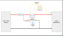
Alright so an update for my wiring diagram. I have made a rough outline of what I think it should look like based what I have gathered so far. I will try to gather a list of components tomorrow. Any input or critiques of this diagram would be appreciated!
 

Attachments

  • Motorcycle Wiring Diagram.pdf
    39.6 KB · Views: 4
An image of the PDF, so it can be viewed directly without downloading
1713334115118.png

If you want to do that yourself, then depending on the program you're using to create the diagram, you may be able to simply use "CTRL-A" (select all) and then "CTRL-C" (copy) on your keyboard, then while you're posting just use "CTRL-V" (paste). If that doesn't work, you can use Alt-Prtsc (copies everything in the current window to the clipboard), open it in a paint program (like MSPaint that comes in Windows, etc), CTRL-V then edit it as desired, then the select-all / copy / paste method to put it right into a post. (or save as an image file like whatever.png and attach it to your post).
 
Regarding the actual diagram, it looks right, but if you want to "automate" precharge and save the second switch, you can use a keyswitch that has multiple positions, like one for ACCessory, Start, etc. Wire up the common to your B+ at the fuse output as you already have, then the first position from OFF goes to the precharge resistor input, and the second position goes to the contactor coil input.
 
But now I wonder, why do you bother with the contactor at all if you already plan on using a breaker?
Security and convenience reasons. The breaker is big and fat, necessitating it to be mounted in a spot Inconvenient for regular use. Which it shouldn't see anyway, it's just for service disconnect. The contactor coil is just 12v, milliamps, so I can mount it anywhere. My preference was to use the keyed ignition to fire the contractor. In this way, the bike will be unable to be driven without the key. I'm using the traditional right handlebar "killswitch" button as the on/off button for the controller.

Just preferences. If OP or anyone else goes with your method, just using the BMS instead of contactor and breaker, they can use the keyed ignition switch wired to the BMS's on/off, if they want a keyed switch to secure their bike.

And honestly? I like the tacticle and audible feedback of the contactor loudly clicking on and off. That's just personal preference. Few things bother me more than a device that requires me to "press and hold this button for 3-10 seconds to turn off."
 
Alright so an update for my wiring diagram. I have made a rough outline of what I think it should look like based what I have gathered so far. I will try to gather a list of components tomorrow. Any input or critiques of this diagram would be appreciated!
You have one diode across your coil, which is fine. If you use two in series, with opposing polarity, your coil with be even better protected. Like this:

|<- ->|

Skip to about 5:30 for a demonstration
 
And honestly? I like the tacticle and audible feedback of the contactor loudly clicking on and off. That's just personal preference. Few things bother me more than a device that requires me to "press and hold this button for 3-10 seconds to turn off."
The only time when you have to press for 6 seconds is when you want to work on the bike.
The rest of the time you just turn the key.

You have one diode across your coil, which is fine. If you use two in series, with opposing polarity, your coil with be even better protected. Like this:
That's used for very fast switching, which really is unnecessary here. Also the goal is to protect the 12V power supply or whatever powers the coil/is directly linked to the electrical path of the coil, not the coil itself.
Keep it simple... ;) :p
 
The diode is not to protect the coil, it is to protect the switch or whatever that is controlling the coil from the voltage spike that comes when relesing the coil.

Also the goal is to protect the 12V power supply or whatever powers the coil/is directly linked to the electrical path of the
Correct both of you, my bad, I miss-typed in my response, I did mean to type switch
 
The only time when you have to press for 6 seconds is when you want to work on the bike.
The rest of the time you just turn the key.
On ANT bms, yes, but really my comment is in regards to press-and-hold buttons for all electrical devices in general, and why I prefer using a contactor, or any manual switch
 
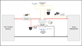
Alright so I've been working on incorporating everyone's feedback and I believe I have come up with a pre-charge contactor circuit that will work for me. Parts have been ordered. :D

For those curious about the components, they are as follows:
72V Coil Contactor
72V SPST Switch
72V SPST Switch
250A Fuse
1k Precharge Resistor
400V 3A Suppression Diodes

1713821829573.png

One thing I am still confused on is where the "Trig -" wire from the contactor should go. Is where I have it in the diagram correct, or should I have it spliced into the "B+" wire?
 
Back
Top