Kelly KLS-H Brushless Motor Controller User’s Manual V 1.2
16
• Make sure the wire is connected correctly
• Turn the PWR switch on.
• The fault code will be detected automatically at restart.
• With the brake switch open, select a direction and operate the throttle. The motor should
spin in the selected direction. Verify wiring or voltage and the fuse if it does not. The motor
should run faster with increasing throttle. If not, refer to the Table 1 code, and correct the
fault as determined by the fault code.
• Take the vehicle off the blocks and drive it in a clear area. It should have smooth
acceleration and good power.
Chapter 4 Programmable Parameters
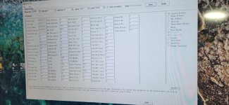
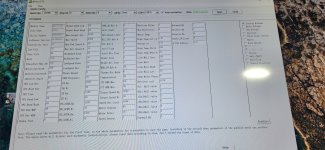
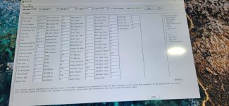
KLS Configuration program allow users to set parameters according to the vehicle actual
working environment so as to be at its best.
The default parameters of the controller are not recommended for all applications. Make
sure set the proper parameters before making any test to avoid danger.
Customers can do program on PC software or Android App. The Android Tablet is prefered.
First of all, people need to do Identification angle function for KLS controller before running the
motor. The controller needs to be connected to batteries, motor and throttle before Identification
operation. That is to say, it is not enough to connect only power supply(PWR=pin7) to batteries
for Identification Angle operation.
Please download the instruction how to use Identification angle function from our website.
www.kellycontroller.com/support.php
4.1 Step 1
(1)Low Volt: The min voltage of reporting this fault - Range 20~115 depending different models
Controller will not operate when battery voltage is near the value so as to protect battery.
Kelly KLS-H Sinusoidal Brushless Permanent Magnet Motor Controller User’s Manual V 1.2
17
Suggestion: Set according to the practical situation. By default, it is set at 20V.
(2)Over Volt: The max voltage of reporting this fault - Range 20~115 depending on different
models
Controller will not operate when battery voltage is higher than the value so as to protect battery
and controller.
Suggestion: Set according to the practical situation.
Please check section 2.4.
(3)Current Percent: Phase Current Percent. Range: 20~100
Functional description: The max motor current is (The Value * Peak Current of the Controller).
Suggestion: Factory default is 100%.
(4)Battery Limit: Battery Limit Current, Limit the max value of Battery Current. Range: 20~100
Functional description: Set max battery current so as to protect battery. A lower value means a
lower battery output current and better protective effect. But excessively low value will affect
acceleration.
Suggestion: Factory default is 100%.
(5)Identification Angle: Please download the instruction to how to use Identification angle
function from the website.
www.kellycontroller.com/support.php
If you can read 85 in Identification Angle item, that is to say, the system is stable and normal.
Please fill in 170 for Identification Angle item in user program. Then
please click Write button in user program. Please wait a few seconds before restart the power
supply. You will see some info on Monitor screen after power supply is
reset. If you see Reset error on the Monitor screen, that is to say, the auto_Identification is
finished. You can see 85 in the Identification Angle item again. And the controller will
blink error code. This is normal. Please reset the power supply again. Then everything will be
fine. The motor is ready to be drived by the KLS controller.
Range: 85 or 170, nothing else.
(6)TPS Low Err: Hall active pedal, if lower than the value, report the fault of TPS Type. Range:
0~20
(7)TPS High Err: Hall active pedal, if higher than the value, report the fault of TPS Type. Range:
80~100
As you may know, the output of hall throttle from Kelly is about from 0.86V to 4.2V.
Our controller will report 3.3 error code if the output of hall throttle is below 0.5V or above 4.5V
by default.
The controller will think the hall throttle is shorted or damaged if the output is beyond the range
from 0.5V to 4.5V.
You can adjust the threshold voltage below or above 0.5V.The controller will report the 3.3 code
to protect the system according to different types of hall throttle.
Because there are many different hall throttle suppliers in the world. The initial output can not be
Kelly KLS-H Brushless Motor Controller User’s Manual V 1.2
18
always in the range of 0.5V to 4.5V.
But it doesn't make any differences if you choose 0-5V or 3-wire pot for the throttle type. That is
to say, these two settings are only useful for hall active throttle or pedal when you chose throttle
type at 2.
As the same goes, it is valid to adjust the high threshold voltage above 4.5V or below 4.5V.
Usually the hall output voltage is 4.2V Max. If you adjust it to lower value which is near 4.2V,it
may trigger the error code in normal way.
(8)TPS Type: TPS Type, 1:0-5V 3-wire 0-5K pot,5K is normal,2K-20K can be used;2:Hall active
throttle or pedal. Range: 1~2
(9)TPS Dead Low: TPS Dead Zone Low. Range: 5~40
Functional description: Set throttle effective starting point
Suggestion: Set according to the practical situation, factory default is 20%*5V=1.0V.
(10)TPS Dead High: TPS Dead Zone High. Range: 60~95
Functional description: Set throttle effective ending point
Suggestion: Set according to the practical situation, factory default is 80%*5V=4.0V.
(11)Brake sensor type: Brake sensor type for brake variable regen mode:
1:0-5V 3-wire 0-5K pot,5K is normal,2K-20K can be used;2:Hall active throttle or pedal. Range:
1~2
(12)Brake sensor Dead Low: Brake sensor Dead Zone Low. Range: 5~40
Functional description: Set throttle effective starting point
Suggestion: Set according to the practical situation, factory default is 20%*5V=1.0V.
(13)Brake sensor Dead High: Brake sensor Dead Zone High. Range: 60~95
Functional description: Set throttle effective ending point
Suggestion: Set according to the practical situation, factory default is 80%*5V=4.0V.
(14)Max output Fre: Max output frequency. Unit:Hz
Functional description: It will affect the top speed of the motor.
Suggestion: Set according to the practical situation, factory default is 1000Hz.Please don’t set it
1000Hz above.
(15)Max Speed: Max Speed [rpm]. Range: 0~15000 By default, it is set at 4000.Software
version 0109 can support 15000RPM settings in user program.
(16)Max Fwd Speed %: The forward speed of the percentage of maximum speed. Range:
20~100 By default, it is set at 100%
(17)Max Rev Speed %: The reverse speed of the percentage of maximum speed. Range:
Kelly KLS-H Sinusoidal Brushless Permanent Magnet Motor Controller User’s Manual V 1.2
19
20~100 By default, it is set at 100%
(18)PWM Frequency: Frequency of PWM operation. Unit: KHz
Functional description:20KHz is better for hub motor with strict quiet control.
Suggestion: Set according to the practical situation, factory default is 20KHz.Please don’t set it
20KHz above.
Value Range:10KHz or 20KHz
(19)Start-up H-Pedal:
Value range: Enable and Disable
Functional description: If enabled, the controller will detect the current pedal status at power up.
If throttle got effective output, the controller will report fault and not operate.
Suggestion: Set according to the practical situation, factory default is Enable.
(20)Brake H-Pedal: Releasing Brake High Pedal Disable
Value range: Enable and Disable
Functional description: If enabled, the controller will detect the current pedal status when
release the brake. If throttle got effective output, the controller will report fault and not operate.
Suggestion: Set according to the practical situation, factory default is Disable.
(21)NTL H-Pedal: Neutral position High Pedal Disable. Only useful when Three gears switch
function is enabled.
If enable, the controller will detect the current pedal position or signal When the switch is in
neutral poistion.
If the throttle got effective output signal, the controller will not operate and report fault code.
Suggestion: Set according to the practical situation, factory default is Disable.
(22)Joystick function:
If enable, the controller can drive the motor on two directions without using any reversing
switch.
Just one single throttle can drive the motor on forward and reversing direction.
The stick shift throttle firmware can be called wig-wag or joystick operation. It is only a software
function. Usually It is useful for electric boat project. You still can use the common 0-5K pot or
0-5V throttle for the controller. If you don't choose the joystick, you operated the throttle in this
way. The motor speed will increase when the throttle is from 0V to 5V.
If you enable joystick for this controller in user program, you will start the motor from 2.5V
position.2.6V to 5V is forward.2.4V to 0V is backward.
2.4V to 2.6V is the throttle dead zone. Customers can adjust the throttle dead zone in user
program also.
Please note the common throttle will spring back to original position if you release the throttle.
Suggestion: factory default is Disable.
(23)Three Gears switch: It is used for function of F-N-R control.
Please check the wiring diagram in the manual for F-N-R control.
Kelly KLS-H Brushless Motor Controller User’s Manual V 1.2
20
Suggestion: Set according to the practical situation, factory default is Disable.
(20-A)Three Gears Switch
Value range: Enable and Disable
Functional description: If enabled, the Forward switch will be activated. Please see figure 4.1.
Suggestion: Set according to the practical situation, factory default is Disable.
(20-B)Foot Switch
Value range: Enable and Disable
Functional description: If enabled, the foot switch will be activated. The controller will not accept
the throttle signal if the foot switch is turned off. Please see figure 4.1.
Suggestion: Set according to the practical situation, factory default is Disable.
Configuration Pin Status Running
Status
Forward
Switch Foot Switch FWD_SW
(12)
REV_SW
(14)
Foot
(15)
Enable Disable
OFF OFF x Neutral
OFF ON x Reverse
ON OFF x Forward
ON ON x Neutral
Disable Enable
x OFF OFF Can’t operate
x ON OFF Can’t operate
x ON ON Reverse
x OFF ON Forward
Disable Disable x OFF x Forward
x ON x Reverse
Note: X means can be on or off
Figure 4.1
(25)If enabled, the controller will output max power for a while.
Boost function is just full throttle position when you turn on boost switch even if the throttle is not
operated at all.
The boost function is still based on limiting of the motor current and battery current settings in
user program.
If disabled, the controller can provide brake sensor regen mode on the same pin as pin2.In
simple, boost and brake analog regen used the same pin as pin2.
Suggestion: Set according to the practical situation, factory default is Disable. So the default
function is brake variable regen mode.
(25)Foot switch: It is used for microswitch. If enabled, the controller will only accept the throttle
signal after received the valid foot switch sig


