Shorted my CA?

Joined
Feb 19, 2022
Messages
19
Stupidly clipped a cable (was switching out the PAS cable with a different connector) while my CA was still on and now it won't turn on. I'm assuming I blew a fuse or something but can't seem to find anything when I open the PCB. Any tips?
 
Which cable was clipped?

If it is one like the main cable, there are battery voltage and logic / signal voltages together, and if battery voltage was shorted to the signals it can blow up the MCU itself. That requires sending it to ebikes.ca to fix, or just buying a new one, depending on the hurry you're in.


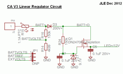
The CA doesn't have a fuse, per se, but some parts can act as one for certain specific situations (not the above one because it's not the current that damages things, it's the voltage, and a fuse doesn't stop that. The power supply system is rather different from most devices. It passes first thru a resistor and LED in the display, then to the input of a FET, and a zener/resistor combo IIRC, before going to the rest of the system. You can look around for my Cycle Analyst Repair thread for a partial schematic of the PSU area, and some explanations by the designer.
 
Thanks @amberwolf . It was the PAS cable (was adding on a voltage regulator and new connector). I don't see any signs of damage but you may be right that it was the MCU, which, if so, is a total gut punch since it was the last step before I was ready to go. This is what I get for rushing at the end... 😔
 
Ok, then to figure out what may have failed, you need to look at what was shorted when you cut it.

Which specific wires are in that cable?
 
Then depending on the sequence of the shorts, the 10v could have been fed back into one of the signal lines; if those go directly to the MCU that could have fried that. (I don't know the specific wiring; if they're buffered it might be ok).

If the 10v was shorted to ground first, it may have just damaged the regulator system itself. That we can test for.

this is the circuit diagram from that thread for the CA V3:

1713736070571.png

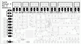
What voltage do you measure at the 10v pin of the CA board at the Torque Sensor pad section?

What voltage do you measure at C5 (about the middle of the board), with battery connected to the CA? If it is about 12v, then the main regulator is working.

1713737866997.png
 
Ugh. Nothing. I can see voltage coming in, but it seems to disappear pretty quick. I don't see anything on the 10v or anywhere else for that matter. Guess it's the MCU?
 
What do you read for voltage at the different points in the regulator circuit? (I'd mark up the diagram I included previously, or the PCB layout, whichever is easier, with the volts you read at each point in that diagrammed circuit). It may have just popped Q1, or maybe D3.

If there is no voltage at the D3 output but is at the input, then D3 is probably popped, and you can use the diode test on the multimeter (with no battery connected to the CA) to test it.

If there is battery voltage at D3, then R24 should have battery on one side, and about 9v on the other, where it connects to Q1 and the zener Z1. If it does, then Q1 will turn on and work. If not, Q1 won't do anything.

If Q1 is working it will have about 12v on the output at C5. If not, Q1 is probably popped. Q1 is a "depletion mode" FET, there's details on what can be used to replace it in the CA repair thread in Justin's posts.

Do you have a 12v supply available? If so, you can connect it to the Q1/C5 junction, that leads to the LED backlight supply input. The CA will power up, but probably show LOW VOLTS right after the boot screen. If so, the MCU is probably ok. This means replacing Q1 would probably fix it, if you have the 9v at Z1/R24.

WIth that 12v supply connected, If the CA doesn't power up but the backlight comes on, and a meter does show 12v at the Q1/C5 junction, the MCU may be toast, or the 5v supply to the MCU might be. I don't have a diagram for any of the power supply or CA other than that small section of the input above.
 
Back
Top