I have Issues with my bike harness wiring

drago9934

1 mW
Joined
Feb 2, 2024
Messages
13
Location
Southampton
Hey,
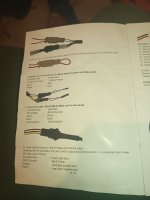
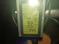
So essentially, Ive stripped a harness cable and it shorted. I've tried to resolder it, I did. But it didn't work properly. I've tested all the connectivity with multimeter and everything to the hall sensor board. I've insulated the cables to the best of my ability. Initially l though that the issue is with the hall sensors. So I've replaced them. I erroneously thought so because when I was measuring some hall sensors were showing no connectivity. But I found out that only certain hall wire colour corresponded to a certain hall sensor. Anyway everything measures fine. I've tried to close the motor, but when I press the throttle nothing happens. I have two throttles. I've swapped, Same story. I've essentially siliconed the new hall sensors that I've swapped but I thought that they might not be making good connection. Later on, I've tested the motor before I put it on the wheel. Everything measures fine. Very rarely though it shows watts going up and down without pressing the throttle like 0-13 and etc. then it disappeared, so I was hoping that it will finally run. When I closed it and connected everything, by turning it on, the throttle doesn't work and the battery appears empty. I'm assuming that it's the red wire that is making contact. It's a new motor I doubt that its the controller. It was working perfectly before I stripped the harness. Hence my suspicion is that something is shorting. I'm not sure why but when I try to check resistance between the halls it doesn't show anything. So essentially, the battery life appears as empty and there is the random watts going up and down. I did my best guys, please some kind soul guide me. Thank you
 
What was the initial problem that caused you to start working on it?

What happened just before that problem occured?

Are all the steps in your post in the exact order they occured? (they seem to be in some other order, but I can't tell which ones happened first, and were done first--the exact order of issues, tests, and results matters for troubleshooting).


Details of the specific parts you have, and a diagram of how they are connected now, marked up with how they were originally connected, may also help us help you.
 
What was the initial problem that caused you to start working on it?

What happened just before that problem occured?

Are all the steps in your post in the exact order they occured? (they seem to be in some other order, but I can't tell which ones happened first, and were done first--the exact order of issues, tests, and results matters for troubleshooting).

The wheel fell off. I wasn't aware that I need torque arms. Got some fixed it. In the process of the wheel falling off it pulled on the harness and it stripped the cables bare. I was hoping that some silicone would prevent it from shorting. To prevent opening. But it shorted. I opened it up. Then I cut and resoldered the faulty wires. Then I tested it again. It was struggling to start slight movement then complete stop. Then I figured that I am dumb and I learnt how to do some basic multimeter tests. Well all the wires make connection with the board( continuity test). Then I tested each one individually. Red probe on the red then black on each left sensor. No problems. Then one probe on the black, tested all middle sensors, no problem. All 0.1, good connectivity. Then all individual hall sensors, and tested the right hall, some were giving connectivity, other not. I assumed that this was the problem changed the board with new hall sensors. Although when I ordered the new one I did the exact same test and got same result. Hence, I figured that the halls turn on only in specific position, ( im still newbie). So I assumed that the halls were alright. I did a resistance test on each phase. By setting the multimeter on 20ohms. They all gave low resistance. I then put it on again. Same problem. Then I wanted to find out how to test for shorts. Found this from a thread In here actually. I've put the red probe on continuity and then, on the black wire. I've got a result of 1780. Which stayed. Then I touched the red to red and with the black tested the halls. They all flashed similarly 1780 but the reading didn't stay. It went back to 1, which is the basic, no connection. I forgot to mention in the beginning I shortened the cable by cutting the faulty section. Im now suspecting that the short is in the harness. I don't really want to order new one since it takes ages to arrive. If it is in the harness is there a way to make them fit around each other and in the groove in the axle. Thanks.
 
The wheel fell off. I wasn't aware that I need torque arms. Got some fixed it. In the process of the wheel falling off it pulled on the harness and it stripped the cables bare. I was hoping that some silicone would prevent it from shorting. To prevent opening. But it shorted. I opened it up. Then I cut and resoldered the faulty wires. Then I tested it again. It was struggling to start slight movement then complete stop. Then I figured that I am dumb and I learnt how to do some basic multimeter tests. Well all the wires make connection with the board( continuity test). Then I tested each one individually. Red probe on the red then black on each left sensor. No problems. Then one probe on the black, tested all middle sensors, no problem. All 0.1, good connectivity. Then all individual hall sensors, and tested the right hall, some were giving connectivity, other not. I assumed that this was the problem changed the board with new hall sensors. Although when I ordered the new one I did the exact same test and got same result. Hence, I figured that the halls turn on only in specific position, ( im still newbie). So I assumed that the halls were alright. I did a resistance test on each phase. By setting the multimeter on 20ohms. They all gave low resistance. I then put it on again. Same problem. Then I wanted to find out how to test for shorts. Found this from a thread In here actually. I've put the red probe on continuity and then, on the black wire. I've got a result of 1780. Which stayed. Then I touched the red to red and with the black tested the halls. They all flashed similarly 1780 but the reading didn't stay. It went back to 1, which is the basic, no connection. I forgot to mention in the beginning I shortened the cable by cutting the faulty section. Im now suspecting that the short is in the harness. I don't really want to order new one since it takes ages to arrive. If it is in the harness is there a way to make them fit around each other and in the groove in the axle. Thanks.

The wheel fell off. I wasn't aware that I need torque arms. Got some fixed it. In the process of the wheel falling off it pulled on the harness and it stripped the cables bare. I was hoping that some silicone would prevent it from shorting. To prevent opening. But it shorted. I opened it up. Then I cut and resoldered the faulty wires. Then I tested it again. It was struggling to start slight movement then complete stop. Then I figured that I am dumb and I learnt how to do some basic multimeter tests. Well all the wires make connection with the board( continuity test). Then I tested each one individually. Red probe on the red then black on each left sensor. No problems. Then one probe on the black, tested all middle sensors, no problem. All 0.1, good connectivity. Then all individual hall sensors, and tested the right hall, some were giving connectivity, other not. I assumed that this was the problem changed the board with new hall sensors. Although when I ordered the new one I did the exact same test and got same result. Hence, I figured that the halls turn on only in specific position, ( im still newbie). So I assumed that the halls were alright. I did a resistance test on each phase. By setting the multimeter on 20ohms. They all gave low resistance. I then put it on again. Same problem. Then I wanted to find out how to test for shorts. Found this from a thread In here actually. I've put the red probe on continuity and then, on the black wire. I've got a result of 1780. Which stayed. Then I touched the red to red and with the black tested the halls. They all flashed similarly 1780 but the reading didn't stay. It went back to 1, which is the basic, no connection. I forgot to mention in the beginning I shortened the cable by cutting the faulty section. Im now suspecting that the short is in the harness. I don't really want to order new one since it takes ages to arrive. If it is in the harness is there a way to make them fit around each other and in the groove in the axle. Thanks.
Also I was worried that the hall board will make connection the metal that closes the motor. I've put silicone on the solder. I've put heat resistant tape on the copper below it. I've epoxied the halls in the groves. I am not sure what should be located where when I close it though. I tried spacing the phases as far as possble from each other.
 
It's a new motor I doubt that it’s the controller. It was working perfectly before I stripped the harness. Hence my suspicion is that something is shorting. I'm not sure why but when I try to check resistance between the halls it doesn't show anything. So essentially, the battery life appears as empty and there is the random watts going up and down. I did my best guys, please some kind soul guide me. Thank you
How did you come to that conclusion? I’m guessing you fried the controller.
 
Hard to say, since you’ve provided a lot of info on the motor, since it’s your conclusion that it’s the problem, but virtually no info on the controller. If you shorted the cable, then sure, if the phase wires shorted to the halls, they could be fried, but only after taking out your controller.
 
Also I was worried that the hall board will make connection the metal that closes the motor. I've put silicone on the solder. I've put heat resistant tape on the copper below it. I've epoxied the halls in the groves. I am not sure what should be located where when I close it though. I tried spacing the phases as far as possble from each other.
Motor is 48v1500w, controller, I have to check. Phases
Hard to say, since you’ve provided a lot of info on the motor, since it’s your conclusion that it’s the problem, but virtually no info on the controller. If you shorted the cable, then sure, if the phase wires shorted to the halls, they could be fried, but only after taking out your controller.
The last two are the controller
 

Attachments

  • IMG_20240202_200419_828.jpg
    IMG_20240202_200419_828.jpg
    4.2 MB · Views: 4
  • IMG_20240202_200353_308.jpg
    IMG_20240202_200353_308.jpg
    3.3 MB · Views: 4
  • IMG_20240202_200349_041.jpg
    IMG_20240202_200349_041.jpg
    3 MB · Views: 4
What was the initial problem that caused you to start working on it?

What happened just before that problem occured?

Are all the steps in your post in the exact order they occured? (they seem to be in some other order, but I can't tell which ones happened first, and were done first--the exact order of issues, tests, and results matters for troubleshooting).


Details of the specific parts you have, and a diagram of how they are connected now, marked up with how they were originally connected, may also help us help you.
This is how wires are connected, two same pictures is the controller.
 

Attachments

  • IMG_20240202_200349_041.jpg
    IMG_20240202_200349_041.jpg
    3 MB · Views: 3
  • IMG_20240202_200353_308.jpg
    IMG_20240202_200353_308.jpg
    3.3 MB · Views: 1
  • IMG_20240202_200624_403.jpg
    IMG_20240202_200624_403.jpg
    3.1 MB · Views: 2
  • IMG_20240202_200642_691.jpg
    IMG_20240202_200642_691.jpg
    3.2 MB · Views: 4
  • IMG_20240202_200650_056.jpg
    IMG_20240202_200650_056.jpg
    3 MB · Views: 4
The wheel fell off. I wasn't aware that I need torque arms. Got some fixed it. In the process of the wheel falling off it pulled on the harness and it stripped the cables bare.

If the motor-to-controller wiring was damaged, then it's easily possible for phases (battery (high) voltage), to short to each other and/or to hall/etc wiring (which is all low-voltage). This can damage or destroy various controller parts, making them either not work at all or work incorrectly. It can also do the same to every part on the bike that was hooked up to the 5v line from the controller, which includes the motor halls, PAS, speed sensor, throttle, sometimes ebrake levers (if they're not the common type with simple switches but the less commmon type that uses hall switches).

The quickest and simplest but most expensive solution is to replace the entire system with a new kit (controller, motor, throttle, etc).

Otherwise you have to find each individual problem first, and fix them all *before* you ever power it back up with the new parts, or else any existing problem still there could damage new parts and end up with you chasing down problems forever.

Wiring would be the first thing to fix--you can buy new motor cabling from Grin Tech ebikes.ca or other places, either as just the cable with wires, or as "extension" cables with the connectors already on them, etc., to match your existing controller connections, but you should measure your existing cable's outer diameter to be sure the new stuff is no larger than that so it will fit thru the axle hole correctly.

Repairing the controller, if something is wrong with it, may be possible, but sometimes the damage is to parts you can't get (like the MCU), or are too difficult to replace even if you can find the parts (like gate drivers and other parts in the phases).

Sometimes it's just the FETs; there are tests you can try for them in the Learn - Troubleshooting section at ebikes.ca (and in many posts around the forum)...but sometimes they pass the tests and still don't work correctly, either because of less drastic damage to them or because the gate drivers aren't working right anymore.

If the 5v supply in the controller is damaged, it won't power up throttle, halls, PAS, MCU, etc correctly.

If the 5v supply still works but the stuff connected to it is damaged, they may not work right or at all even though they're getting power. You can use the multimeter set to 20VDC to measure the red and black wires from controller to throttle, halls, PAS, and see what voltage each one gets.


There's quite a few threads over the years on this type of problem (axle wiring damage), some of which have long chains of troubleshooting steps in them, if you poke around.
 
Last edited:
This is how wires are connected, two same pictures is the controller.
It looks like you’re running headless (no display). Can you confirm?
When you said the battery appeared to be empty, how did you determine that?

Generally, if you shorted phase wires, phase to phase,or phase to ground, you likely fried the MOSFETs. If you shorted phase to a hall signal, you likely fried the hall detection circuit and possibly the 5v supply. If you shorted phase to the 5v hall supply wire, then you probably fried the 5v dc supply. If you shorted the 5v to ground, you probably fried the 5v supply as well.

If you turn the controller on, you could check voltage on either the red throttle wire from the controller or PAS, if you use it, to see if 5v is still present. If 5v is present, then I’d open the controller to see if there are funny smell or obvious damage to the FETs.
 
If the motor-to-controller wiring was damaged, then it's easily possible for phases (battery (high) voltage), to short to each other and/or to hall/etc wiring (which is all low-voltage). This can damage or destroy various controller parts, making them either not work at all or work incorrectly. It can also do the same to every part on the bike that was hooked up to the 5v line from the controller, which includes the motor halls, PAS, speed sensor, throttle, sometimes ebrake levers (if they're not the common type with simple switches but the less commmon type that uses hall switches).

The quickest and simplest but most expensive solution is to replace the entire system with a new kit (controller, motor, throttle, etc).

Otherwise you have to find each individual problem first, and fix them all *before* you ever power it back up with the new parts, or else any existing problem still there could damage new parts and end up with you chasing down problems forever.

Wiring would be the first thing to fix--you can buy new motor cabling from Grin Tech ebikes.ca or other places, either as just the cable with wires, or as "extension" cables with the connectors already on them, etc., to match your existing controller connections, but you should measure your existing cable's outer diameter to be sure the new stuff is no larger than that so it will fit thru the axle hole correctly.

Repairing the controller, if something is wrong with it, may be possible, but sometimes the damage is to parts you can't get (like the MCU), or are too difficult to replace even if you can find the parts (like gate drivers and other parts in the phases).

Sometimes it's just the FETs; there are tests you can try for them in the Learn - Troubleshooting section at ebikes.ca (and in many posts around the forum)...but sometimes they pass the tests and still don't work correctly, either because of less drastic damage to them or because the gate drivers aren't working right anymore.

If the 5v supply in the controller is damaged, it won't power up throttle, halls, PAS, MCU, etc correctly.

If the 5v supply still works but the stuff connected to it is damaged, they may not work right or at all even though they're getting power. You can use the multimeter set to 20VDC to measure the red and black wires from controller to throttle, halls, PAS, and see what voltage each one gets.


There's quite a few threads over the years on this type of problem (axle wiring damage), some of which have long chains of troubleshooting steps in them, if you poke around.
It looks like you’re running headless (no display). Can you confirm?
When you said the battery appeared to be empty, how did you determine that?

Generally, if you shorted phase wires, phase to phase,or phase to ground, you likely fried the MOSFETs. If you shorted phase to a hall signal, you likely fried the hall detection circuit and possibly the 5v supply. If you shorted phase to the 5v hall supply wire, then you probably fried the 5v dc supply. If you shorted the 5v to ground, you probably fried the 5v supply as well.

If you turn the controller on, you could check voltage on either the red throttle wire from the controller or PAS, if you use it, to see if 5v is still present. If 5v is present, then I’d open the controller to see if there are funny smell or obvious damage to the FETs.

0.5 for throttle . I stuck the DC In throttle black and red wires while on. I got 0.5, even after I pressed the throttle. Can you confirm that this is the correct way to measure ?
 

Attachments

  • IMG_20240202_202536_897.jpg
    IMG_20240202_202536_897.jpg
    3.3 MB · Views: 4
0.5 for throttle . I stuck the DC In throttle black and red wires while on. I got 0.5, even after I pressed the throttle. Can you confirm that this is the correct way to measure ?
Hall sensors, I tested by placing the black probe on the ground and red on each individually. I got a reading of 1 v max. Voltmeter was on 20dc.
 
It looks like you’re running headless (no display). Can you confirm?
When you said the battery appeared to be empty, how did you determine that?

Generally, if you shorted phase wires, phase to phase,or phase to ground, you likely fried the MOSFETs. If you shorted phase to a hall signal, you likely fried the hall detection circuit and possibly the 5v supply. If you shorted phase to the 5v hall supply wire, then you probably fried the 5v dc supply. If you shorted the 5v to ground, you probably fried the 5v supply as well.

If you turn the controller on, you could check voltage on either the red throttle wire from the controller or PAS, if you use it, to see if 5v is still present. If 5v is present, then I’d open the controller to see if there are funny smell or obvious damage to the FETs.
I'm not familiar with that terminology. Could you please explain it to me if it's fixable, what do I need to do. I am grateful. Or if not should I replace. I have all the tools needed to fix. Thanks. So phase to 5v supply.
 
Should be 5v. You likely fried the 5v supply.
I have this spare controller, will it work if I swap them ? Seems to be almost the same. What tests do I need to do to determine everything. Sorry for the many questions. Started learning about this a week ago..
 

Attachments

  • IMG_20240202_200419_828.jpg
    IMG_20240202_200419_828.jpg
    4.2 MB · Views: 2
If the motor-to-controller wiring was damaged, then it's easily possible for phases (battery (high) voltage), to short to each other and/or to hall/etc wiring (which is all low-voltage). This can damage or destroy various controller parts, making them either not work at all or work incorrectly. It can also do the same to every part on the bike that was hooked up to the 5v line from the controller, which includes the motor halls, PAS, speed sensor, throttle, sometimes ebrake levers (if they're not the common type with simple switches but the less commmon type that uses hall switches).

The quickest and simplest but most expensive solution is to replace the entire system with a new kit (controller, motor, throttle, etc).

Otherwise you have to find each individual problem first, and fix them all *before* you ever power it back up with the new parts, or else any existing problem still there could damage new parts and end up with you chasing down problems forever.

Wiring would be the first thing to fix--you can buy new motor cabling from Grin Tech ebikes.ca or other places, either as just the cable with wires, or as "extension" cables with the connectors already on them, etc., to match your existing controller connections, but you should measure your existing cable's outer diameter to be sure the new stuff is no larger than that so it will fit thru the axle hole correctly.

Repairing the controller, if something is wrong with it, may be possible, but sometimes the damage is to parts you can't get (like the MCU), or are too difficult to replace even if you can find the parts (like gate drivers and other parts in the phases).

Sometimes it's just the FETs; there are tests you can try for them in the Learn - Troubleshooting section at ebikes.ca (and in many posts around the forum)...but sometimes they pass the tests and still don't work correctly, either because of less drastic damage to them or because the gate drivers aren't working right anymore.

If the 5v supply in the controller is damaged, it won't power up throttle, halls, PAS, MCU, etc correctly.

If the 5v supply still works but the stuff connected to it is damaged, they may not work right or at all even though they're getting power. You can use the multimeter set to 20VDC to measure the red and black wires from controller to throttle, halls, PAS, and see what voltage each one gets.


There's quite a few threads over the years on this type of problem (axle wiring damage), some of which have long chains of troubleshooting steps in them, if you poke around.
I've checked the voltage to the
Hi drago9934,

BEFORE you try a different controller, I suggest you take a better and closer look at testing your BLDC motor and wiring.
Please take a look at this thread for bench tests and tips to make on your motor and wiring before powering it up!

Testing BLDC motor's Phase Wiring - Hall Sensors and Wiring. - Electricbike.com Ebike Forum


Regards,
T.C.
Hey, I have done most of these tests. But thanks to these people above I am certain that it is the controller. Just watched some videos on how to test it. I am getting no 5v from it as well. But thanks anyway. Appreciate it.
 
I have this spare controller, will it work if I swap them ? Seems to be almost the same. What tests do I need to do to determine everything. Sorry for the many questions. Started learning about this a week ago..
No problem. Just take it slow, and always try to test before making any connection (follow TommyCat’s guidance). If the motor checks out, then it’s likely the other controller will work.
 
Remember that the wire damage probably caused the 5v failure (and possibly other problems).

So if you aren't absolutely certain that you've fixed the wiring, correctly and fully, and that the devices that were connected to 5v on the failed controller are not damaged, I strongly recommend making sure this is true before connecting the spare controller.

Otherwise, anything that's still damaged may destroy the spare controller as well.
I'll double check. Thank you
 
Back
Top