Mayham
1 µW
Okay soooo I have a Delfast 3.0 and everything was great until I had axel post shear off on my cord side which I was able to jimmy back together here and there but after about a month I had a catastrophic failure.
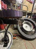
So I opted to get a higher powered hub motor than what was on there previously which albeit was a quick little motor, I still craved the need the need for speed, so I went from a 72v 5k to 72v 8k hub motor which after a month of waiting and $1000 it finally arrived from China which was a week or two ago…
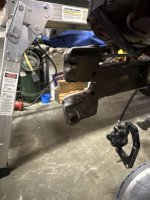
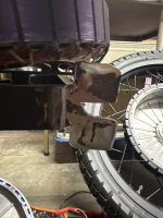
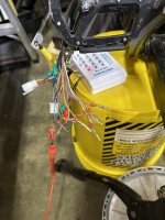
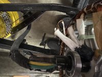
I ended up getting a QS275 V3 WP40H ( link to actual product I got) hub motor, controller this that and the other thing basically everything short of the frame, battery and front tire. So after struggling with removing the Gates Carbon Belt Drive freewheel from the Delfast hub which required of course a special tool/modified socket that I didn’t have, some welding, a whole lot of patience and sweat off It came and I had the new hub motor, controller, throttle and whatever else was needed to get up and going! However that victory was short lived as what would prove to be not enough drop out modification & fabrication was done to help prevent axel spinning and cord wrap, you see as the Delfast hub slowly died it required a lot of removing and installing in its final days which did a magnificent job in rounding out the rear wheel squared off slots for the axel to slide in which as I eluded to helps prevent axel spinning (see picks of modified drop out slots!) So after getting everything up and operational I went to give it a little throttle to pop it out through the pedestrian door of our garage which it was at this time things would take a dramatic turn!
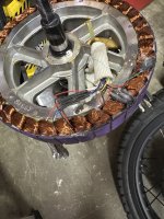
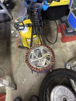
Power to hub died and have t regained it since I’ve tested everything I could with the wheel still intact and got no where. I’m getting the code 07 on the Sabvoton controller so naturally everyone is like it’s the hall sensor which you’ve got me help an eighth of an inch or a 90° cord wrap on the axle is enough to actually pull or dislodge or dislocate the wires going to the hall sensor inside the hub It’s impossible! But sure enough I took the damn thing apart and the only test I could run on the hall sensors even with a rms multimeter and a fancy e-bike tester box was a continuity test. So everything passed the continuity test except the blue hall sensor. So I was prepared and started the repair happy as a pig in s*** until it dawned on me and I checked it to confirm it, after disconnecting the hall sensor 1. QUESTION #1 Shouldn’t the continuity test work or ring true ( no pun intended) after disconnecting the “Faulty” hall sensor?
Update: Just checked and the Blue hall sensor wire and the ground wire to all hall sensor locations both sides of the motor so 6 total location lacks continuity which leads me to believe there’s a short in my hub wire harness somewhere. Can anyone confirm or deny this finding?!
I don’t even know where the short could possibly even be in this motor to be honest!
Btw this motor lacks a hall sensor PCB board!
So I opted to get a higher powered hub motor than what was on there previously which albeit was a quick little motor, I still craved the need the need for speed, so I went from a 72v 5k to 72v 8k hub motor which after a month of waiting and $1000 it finally arrived from China which was a week or two ago…
I ended up getting a QS275 V3 WP40H (
link to actual product I got) hub motor, controller this that and the other thing basically everything short of the frame, battery and front tire. So after struggling with removing the Gates Carbon Belt Drive freewheel from the Delfast hub which required of course a special tool/modified socket that I didn’t have, some welding, a whole lot of patience and sweat off It came and I had the new hub motor, controller, throttle and whatever else was needed to get up and going! However that victory was short lived as what would prove to be not enough drop out modification & fabrication was done to help prevent axel spinning and cord wrap, you see as the Delfast hub slowly died it required a lot of removing and installing in its final days which did a magnificent job in rounding out the rear wheel squared off slots for the axel to slide in which as I eluded to helps prevent axel spinning (see picks of modified drop out slots!) So after getting everything up and operational I went to give it a little throttle to pop it out through the pedestrian door of our garage which it was at this time things would take a dramatic turn! Power to hub died and have t regained it since I’ve tested everything I could with the wheel still intact and got no where. I’m getting the code 07 on the Sabvoton controller so naturally everyone is like it’s the hall sensor which you’ve got me help an eighth of an inch or a 90° cord wrap on the axle is enough to actually pull or dislodge or dislocate the wires going to the hall sensor inside the hub It’s impossible! But sure enough I took the damn thing apart and the only test I could run on the hall sensors even with a rms multimeter and a fancy e-bike tester box was a continuity test. So everything passed the continuity test except the blue hall sensor. So I was prepared and started the repair happy as a pig in s*** until it dawned on me and I checked it to confirm it, after disconnecting the hall sensor 1. QUESTION #1 Shouldn’t the continuity test work or ring true ( no pun intended) after disconnecting the “Faulty” hall sensor?
Update: Just checked and the Blue hall sensor wire and the ground wire to all hall sensor locations both sides of the motor so 6 total location lacks continuity which leads me to believe there’s a short in my hub wire harness somewhere. Can anyone confirm or deny this finding?!
I don’t even know where the short could possibly even be in this motor to be honest!
Btw this motor lacks a hall sensor PCB board!