Ilya
1 mW
Hey
I never had an electrical problem before, so this is completely new to me, but I want to learn.
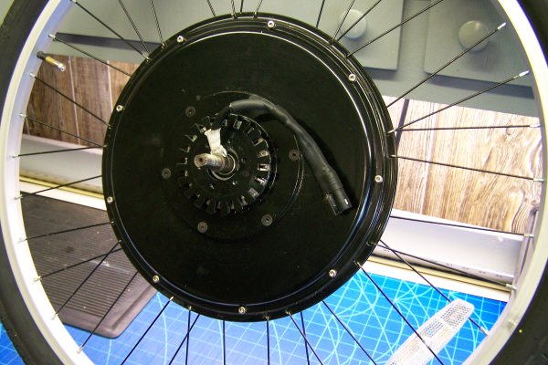
I have a 36V, 250W, unknown ananda rear motor hub ebike , that recently started behaving as if it had a bad contact. It worked flawlessly for the most part of 550 km, apart from some resolved mechanical issues.
A couple of weeks ago power transmission would cease for short intervals with the motor making a rusty noise. Then it got more frequent up to the current point where there are only short intervals with motor power. Initially I thought road bumps (bad contact?) or upward slopes (temperature?) could affect the problem, but it could not always be reproduced. The Ananda D16 screen showed an error symbol with some printed out error code 25 (hall sensor).
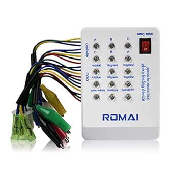
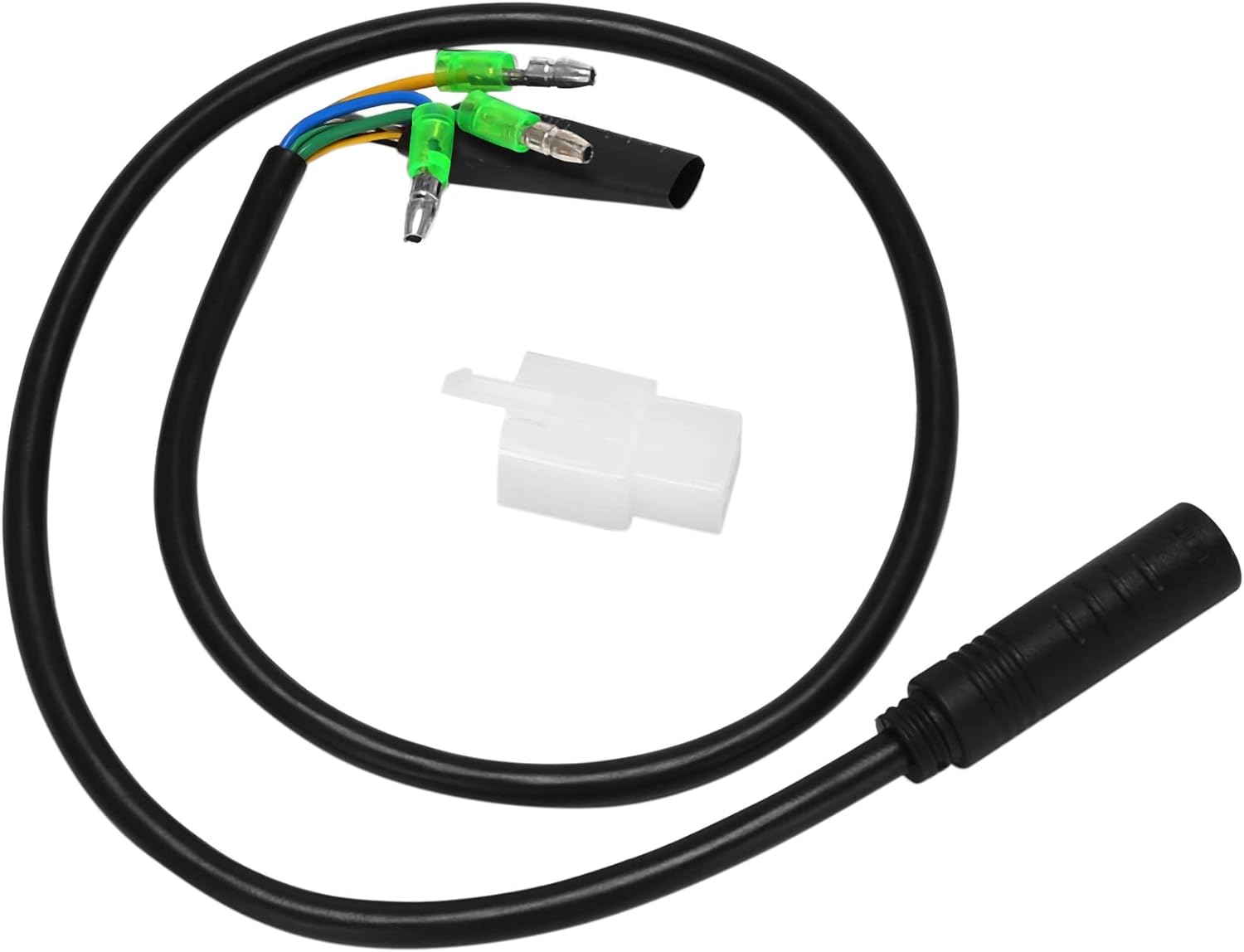
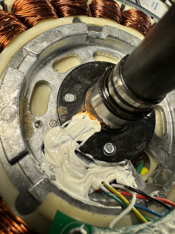
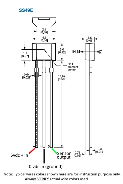
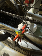
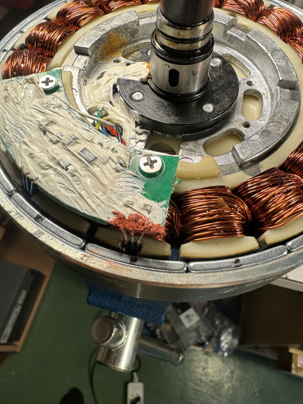
I ended up buying the "generic motor tester" and a cable to connect it with. Turns out the blue hall sensor was always lit. When checking with a multimeter the voltage cycled between 0-2V. Other two 0-3.5V. Aha, sure enough, bad hall sensor I thought, so I opened the motor hub (easier said than done). I checked all the connections OK despite the silicone. Removing the hall was supposed to be the easy part according to the guides I watched, but the wires disconnected from the sensor as I tried to grab it with some pliers. Drilling it to dust was the worst part, as I could not identify the specific sensor afterwards. Connections OK after soldering an amazon bought S49E (3-6.5V operation) and applying new silicone.
A test with the "generic motor tester" showed a pattern to repeat consistenly with 6 unique entries, with the blue now turning on and off from time to time. Problem resolved I thought. But now I have a quite consistent Error 25 from start, only rarely the motor gets an impulse to power. Same result with the "generic motor tester" after assembling everything. Voltage checks shows the same old two 0-3.5V, and the new blue 0-4.5V. Is this bad?
- Do I have to change the other two to the same sensor? Change the new one to one of the old types? If so, any idea which one?
- When I look at it now the "generic motor tester"-pattern is somewhat sketchy:
0 : off
1 : on
Blue-Green-Yellow
000
001
101 ---? should be 011?
111
110
010 ---? should be 100?
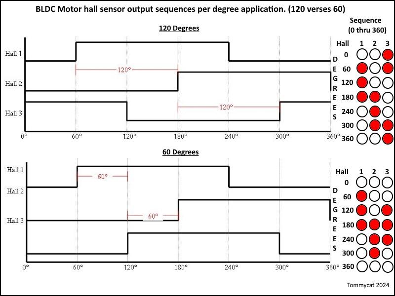
The "generic motor tester"-manual states the normal pattern to be:
000
100
110
111
011
001
for 60 and 120 deg both.
It seems like my pattern can't be compatible with motor operation? Seems like my pattern holds three zeroes or ones in a row per color, but that they overlap out of phase. The replaced/new blue sensor needs to move down 2 places. Sensor out of phase (if that's a thing)? What can I do to resolve this?
I never had an electrical problem before, so this is completely new to me, but I want to learn.
I have a 36V, 250W, unknown ananda rear motor hub ebike , that recently started behaving as if it had a bad contact. It worked flawlessly for the most part of 550 km, apart from some resolved mechanical issues.
A couple of weeks ago power transmission would cease for short intervals with the motor making a rusty noise. Then it got more frequent up to the current point where there are only short intervals with motor power. Initially I thought road bumps (bad contact?) or upward slopes (temperature?) could affect the problem, but it could not always be reproduced. The Ananda D16 screen showed an error symbol with some printed out error code 25 (hall sensor).
I ended up buying the "generic motor tester" and a cable to connect it with. Turns out the blue hall sensor was always lit. When checking with a multimeter the voltage cycled between 0-2V. Other two 0-3.5V. Aha, sure enough, bad hall sensor I thought, so I opened the motor hub (easier said than done). I checked all the connections OK despite the silicone. Removing the hall was supposed to be the easy part according to the guides I watched, but the wires disconnected from the sensor as I tried to grab it with some pliers. Drilling it to dust was the worst part, as I could not identify the specific sensor afterwards. Connections OK after soldering an amazon bought S49E (3-6.5V operation) and applying new silicone.
A test with the "generic motor tester" showed a pattern to repeat consistenly with 6 unique entries, with the blue now turning on and off from time to time. Problem resolved I thought. But now I have a quite consistent Error 25 from start, only rarely the motor gets an impulse to power. Same result with the "generic motor tester" after assembling everything. Voltage checks shows the same old two 0-3.5V, and the new blue 0-4.5V. Is this bad?
- Do I have to change the other two to the same sensor? Change the new one to one of the old types? If so, any idea which one?
- When I look at it now the "generic motor tester"-pattern is somewhat sketchy:
0 : off
1 : on
Blue-Green-Yellow
000
001
101 ---? should be 011?
111
110
010 ---? should be 100?
The "generic motor tester"-manual states the normal pattern to be:
000
100
110
111
011
001
for 60 and 120 deg both.
It seems like my pattern can't be compatible with motor operation? Seems like my pattern holds three zeroes or ones in a row per color, but that they overlap out of phase. The replaced/new blue sensor needs to move down 2 places. Sensor out of phase (if that's a thing)? What can I do to resolve this?
Last edited:
") ).
).