oldswamm
100 W
I kept seeing people question the feasibility of putting TO247 FETs on an Xie-Chang type board. I was thinking of making a 'here's how I would do it' post, then decided to just do it.
Anyway, here's how I'd do it. :wink:


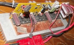
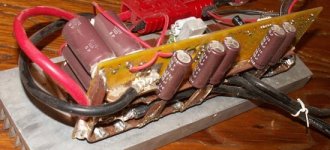
This is a prototype for an EB818 converted to TO247. Drilled every other hole larger, removed most of the traces near the FETs, soldered bus bars (flattened copper tubing), to the board, drilled holes near each source and drain lug and soldered 10ga solid so it contacts the lead up to the FET case (will change that part of the design so they're easier to solder) and to the bus bars. The gates are driven through ferrite beads (removed from a prototype for a FET audio amp I built 15 or 20 years ago).
I didn't have 'ultimate' FETs so used 75A rated parts. I didn't even have 12 identical parts, so I used Fairchild FDH3632s on the top (faster and easier to drive), and Fairchild HUF75652s on the low side (slower, but much better heat dissipation).
Capacitors are mounted upright on top of the board (I decided right off that it wouldn't fit in a standard case), and enough are added to the bottom, connected to the bus through flat copper to bring the total up to about 4000mfd. There are also some 14 MLCC added at various places as near the high side drains as possible. I used 20 .01 1W smt resistors for the shunt, because I had them. Among other changes on farther controller builds of this kind, I would use .090" flat copper instead of flattened tubing. The transistors are soldered to copper heat spreaders (I haven't attached it to the heat sink yet, just laying there....) Some of the things that are strange, such as extra resistors in the PS are because I intend to bed (or at least heavily coat) the board, and wanted to reduce peak temperatures.
Oh, I should mention that the prototype doesn't work (yet). With power on, not much happens, with the hall connector hooked up, it's like 'lock' is on. The wheel can be turned by hand, but stops at the next pole. The throttle has no effect. I need to put some test points on it so I can 'look' at it without shorting it (the only o-scope probe I can find has a tip like a multimeter, and no 'tips/adapters'). I've been spending most of my time working on the rest of the bikes electronics (and keeping the one I'm ridding operational) (and trying to stay warm, it never got above 0F in Nov, then started raining in DEC ), and only seem to pick this board up every week or two. It was two weeks between 'finishing' it and soldering on the power and phase wires, then more than a week before I soldered on the throttle and hall wires and a programming header, then I had to work up the courage to connect it up.....
Laying on one of the heat spreaders is one of the driver boards for the 6FET I'm planing to build next. These are the first PCboards I've built in over a decade, and I had problems at each stage, including having to buy an HP printer (Brother apparently uses a higher temp toner ). Will use Fairchild FDH055N15A FETs. Interesting device, 2 FETs in one case! 5.5mOhm (max) 150V. The driver board uses FAN7392, and can connect to the gate through ferrite beads or the gate lead can be bent out, cut, and soldered flat to the board, in which case there is probably less than 10mm from the driver case to where the gate enters the transistor case, including the gate resistor.
I have a driver board designed for 18 to 12 FET conversions, but as long as I'm using 9C motors, I don't really need it......
If someone has a 9 or 18 FET, programmable board that has excess damage in the FET area, or bad drivers, but a good CPU, that you could let me have cheap, please PM me. Money (lack thereof), is the main thing limiting both this and the control/interface electronics development.
I also have some FGA180N33A I would love to build one of these up around. A 180A 330V IGBT with only about 1Vec, and easy to drive. The driver boards are designed for 300V plus.
Here's the url for the electronics mentioned earlier: ebike control electronics
Thanks for reading,
Bob
Anyway, here's how I'd do it. :wink:


This is a prototype for an EB818 converted to TO247. Drilled every other hole larger, removed most of the traces near the FETs, soldered bus bars (flattened copper tubing), to the board, drilled holes near each source and drain lug and soldered 10ga solid so it contacts the lead up to the FET case (will change that part of the design so they're easier to solder) and to the bus bars. The gates are driven through ferrite beads (removed from a prototype for a FET audio amp I built 15 or 20 years ago).
I didn't have 'ultimate' FETs so used 75A rated parts. I didn't even have 12 identical parts, so I used Fairchild FDH3632s on the top (faster and easier to drive), and Fairchild HUF75652s on the low side (slower, but much better heat dissipation).
Capacitors are mounted upright on top of the board (I decided right off that it wouldn't fit in a standard case), and enough are added to the bottom, connected to the bus through flat copper to bring the total up to about 4000mfd. There are also some 14 MLCC added at various places as near the high side drains as possible. I used 20 .01 1W smt resistors for the shunt, because I had them. Among other changes on farther controller builds of this kind, I would use .090" flat copper instead of flattened tubing. The transistors are soldered to copper heat spreaders (I haven't attached it to the heat sink yet, just laying there....) Some of the things that are strange, such as extra resistors in the PS are because I intend to bed (or at least heavily coat) the board, and wanted to reduce peak temperatures.
Oh, I should mention that the prototype doesn't work (yet). With power on, not much happens, with the hall connector hooked up, it's like 'lock' is on. The wheel can be turned by hand, but stops at the next pole. The throttle has no effect. I need to put some test points on it so I can 'look' at it without shorting it (the only o-scope probe I can find has a tip like a multimeter, and no 'tips/adapters'). I've been spending most of my time working on the rest of the bikes electronics (and keeping the one I'm ridding operational) (and trying to stay warm, it never got above 0F in Nov, then started raining in DEC
Laying on one of the heat spreaders is one of the driver boards for the 6FET I'm planing to build next. These are the first PCboards I've built in over a decade, and I had problems at each stage, including having to buy an HP printer (Brother apparently uses a higher temp toner
I have a driver board designed for 18 to 12 FET conversions, but as long as I'm using 9C motors, I don't really need it......
If someone has a 9 or 18 FET, programmable board that has excess damage in the FET area, or bad drivers, but a good CPU, that you could let me have cheap, please PM me. Money (lack thereof), is the main thing limiting both this and the control/interface electronics development.
I also have some FGA180N33A I would love to build one of these up around. A 180A 330V IGBT with only about 1Vec, and easy to drive. The driver boards are designed for 300V plus.
Here's the url for the electronics mentioned earlier: ebike control electronics
Thanks for reading,
Bob

