Designing the ultimate (400A+) motor controller - what features should it have?

Joined
May 25, 2018
Messages
197
After several iterations of designing various controllers (https://endless-sphere.com/forums/viewtopic.php?f=30&t=109999) I have designed a controller that (should be able to) do 500 peak amps (600A of FETs) in a 100x70x25mm (including heatsink) package. I (and the rest of my startup) are in the process of patenting the interconnect method for the power stage, so I can't share details on that part until the provisional patent is accepted (est. 3 months).

To drive this power stage, I have designed a prototype Teensy 4.0-based control board that I plan on possibly open-sourcing after a while. Our stock firmware will be proprietary but the board will most likely be eventually VESC, etc. compatible.

So far, the board has the following features:
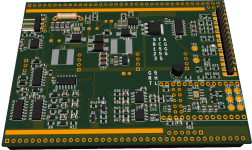
  • Sensored FOC [Working]
  • Temperature sensing for the motor (external), CAPs, and FETs [Working]
  • Throttle control and regenerative braking [Working]
  • Fast (2uS) hardware overcurrent and overvoltage protection. [Working]
  • Integrated on/off switch with zero battery drain (excl. CAP leakage) [Working]
  • Custom speed-torque curves for throttle inputs [In development]
  • Field weakening [In development]
  • Sensorless FOC [In development]
  • Sensorless winding temperature measurement [In development]
  • Sensorless from standstill [In development]
  • CAN-Bus protocol, probably CANOpen [Hardware feature, no software yet]
  • Serial command-line programming interface [Hardware feature, no software yet]
uEBAC-render.png

Additional features that I plan on implementing:
  • IMU chip for traction control and [later] wheelie control
  • Compatibility with pulse-based RC radio receivers
  • Programming through LED and button like R/C ESCs [Maybe]
  • "Hubwoofer" to make the motor sound like an engine or play audio [Maybe, only if you have a clamping torque arm]

Are there any other features that I should have?

Edit after community feedback: Here are some more planned features that people want:
  • Ability to do MPPT using the hubmotor's inductance and a step-up transformer to make 120VAC. Turn your eBike into a powerwall. 1kVA transformers are going for $100 used right now so I'l definitely be using this feature myself.
  • Switchable 12v output for running cooling fan for above mentioned transformer
  • Waterproof, fully potted electronics - I'll pot the control and power stages separately and silicone them together. If a FET ever does fail the control stage can be reused by prying the controller apart with a knife. Likewise, if the control section is damaged by ex. an inadvertent battery wire touching an I/O pin, the power stage can be reused. I already planned this but am listing it here since users mentioned it.
  • Optional integrated precharge circuit to prevent arcs when connecting the battery
  • Compatibility with SIN/COS position sensors by using spare analog inputs - there will be 4 total
  • 150v FETs for higher voltage setups - Can do after the 100v line is released
  • Bluetooth dongle - This will be built into the display and the controller will be password-lockable over CAN.
  • Cruise control - I can easily add support for this plus a three speed switch by using one of the spare analog inputs and resistors between the controller and the switches.
  • Swappable daughterboards that plug into the I/O header on the side for compatibility with various setups (e.g. Chinese hub kit, CycleAnalyst, EggRider ETC)

Note to moderators: I am discussing the portion of the controller that will be open sourced and am not selling these yet. Therefore I believe that this still belongs in the "motor technology" section. I'll move to the buy/sell section when I commercialize this.
 
- precharge
- integrated buck converter for peripherals
- turn signal control
- SOC estimator through coloumb counting

Just some ideas :D
 
c.wagner said:
- precharge
- integrated buck converter for peripherals
- turn signal control
- SOC estimator through coloumb counting

Just some ideas :D

Having damaged my fair share of connectors from arcing, the precharge is something I will probably add. The only disadvantage is that I will have to run the battery current through another MOSFET, increasing losses. For smaller controllers with less than 200 peak battery amps, it will be doable with a single 300A TOLL FET. I'll definitely add this to my 150Apk and 300Apk controllers. I'll probably end up implementing this with a PCB that interrupts either VBATT or GND, contains resistors and FETs, and solders onto the side of the controller with the + and - tabs.

The latter three will require additional hardware, since not everyone will use them. For SOC estimation, speedometer, turn signal I will have a display unit similar to the CycleAnalyst. The controller already has battery current measurement so a combination of voltage measurement and coulomb counting will give a pretty good SOC estimation.

The integrated buck converter will also be an add-on. Something that does 12v10a continuous and 12v25a peak should be fairly easy to make the same width and height as the controller, and can be potted with the main electronics package. With the level of power that this thing is putting out, it better be able to power accessories required for street-legal motorcycles.

Thank you for your feedback.
 
thor- any estimate on delivering sensorless FOC, and from standstill? Tough ones from my very basic understanding...

And this would be programmed through your own publicly released software?

Will it eventually be capable of safely running a 36n42p T-motor U15 @15s? Had a catastrophic fail with another commercially available ESC the other day, so high and dry for now...

You are somewhere in the US as I am?
 
thorlancaster328 said:
[*]Throttle control and regenerative braking [Working]
[*]Custom speed-torque curves for throttle inputs [In development]

Is/can this be adjustable voltage range to customize for a specific hardware throttle already on a system?

Is/can this be separate inputs for throttle and braking? (it's much easier/safer for me to ride with separate acceleration and braking controls, so I have a cable operated throttle for braking on a regular brake lever, as well as a COT on a thumb throttle). So a separate curve choice for the braking input would be useful, so that different responses to the different controls can be created.

Can the braking also be down to zero, meaning that it can "hold" a position when stopped, as long as motor/controller temperatures don't rise too quickly? (Lebowski had this feature at some point in his brain board but took it out, AFAICR). It would be pretty useful to me on my flat-ground applications, stopping at traffic lights, etc. (I can use mechanical brakes to take over when this is insufficient or inapplicable like on slopes or hills).


[*]Sensorless FOC [In development]
[*]Sensorless from standstill [In development]
This is one I'd really like to see (didn't Lebowski have this working well in some version of his brain board?)

Can you add support for different encoder types (not just the common UVW, but SIN/COS, etc)? That way for systems and applications where sensored use works better, it could be done more precisely than the typical UVW, for those motors that have that type of sensing available. (like a powerchair motor I have, for instance).


My applications are heavy cargo bikes/trikes that need to be able to start from a complete stop under heavy load with no human power input at the startup (only later once rolling), even on slopes/uphills.
 
Barncat said:
thor- any estimate on delivering sensorless FOC, and from standstill? Tough ones from my very basic understanding...
Sensorless from standstill is somewhat difficult but not that hard. My current implementation (as well as Lebowski's) relies on knowing the inductance of each phase in real-time and comparing it to the expected inductance at the current through that phase. By doing that and feeding the results to a PLL you can get a good estimate of where the rotor is. The high bandwidth (300khz @ -3db) current sensors in my design will help with this a lot as well.

And this would be programmed through your own publicly released software?
Yes, the controller will be fully programmable by the end-user, much like the Grin Phaserunner. It will most likely be a HTML5-based PWA that uses the HTML5 Serial port API to communicate.

Will it eventually be capable of safely running a 36n42p T-motor U15 @15s? Had a catastrophic fail with another commercially available ESC the other day, so high and dry for now...
This task will be quite easy for the 500 phase amp model. Our prototype controller has considerably more inductance in the power stage than the new SMD-based design and can handle a hubmotor with ~1/3 the inductance of (my daily driver's) QS205 3T just fine.
You are somewhere in the US as I am?
Yes, I am located in Bozeman, MT.
 
amberwolf said:
Is/can this be adjustable voltage range to customize for a specific hardware throttle already on a system?

Is/can this be separate inputs for throttle and braking? (it's much easier/safer for me to ride with separate acceleration and braking controls, so I have a cable operated throttle for braking on a regular brake lever, as well as a COT on a thumb throttle). So a separate curve choice for the braking input would be useful, so that different responses to the different controls can be created.

Can the braking also be down to zero, meaning that it can "hold" a position when stopped, as long as motor/controller temperatures don't rise too quickly? (Lebowski had this feature at some point in his brain board but took it out, AFAICR). It would be pretty useful to me on my flat-ground applications, stopping at traffic lights, etc. (I can use mechanical brakes to take over when this is insufficient or inapplicable like on slopes or hills).
Yes, the controller will be adaptable to different throttles / throttle curves. It will have a 0% voltage, 10% voltage ... 100% voltage for the throttle(s) that will be configurable from the software, similar to the PhaseRunner. The controller will also allow use of the second throttle input as a brake by specifying a negative torque value for that throttle.

The braking does go down to zero, it's FOC and torque can be applied at any speed as long as the controller knows where the rotor is. I have this in my bike and slowing to a stop doesn't cause undue heating, even with a slight hill. If you have steeper hills you will definitely need mechanical brakes as you said.

Can you add support for different encoder types (not just the common UVW, but SIN/COS, etc)? That way for systems and applications where sensored use works better, it could be done more precisely than the typical UVW, for those motors that have that type of sensing available. (like a powerchair motor I have, for instance).

My applications are heavy cargo bikes/trikes that need to be able to start from a complete stop under heavy load with no human power input at the startup (only later once rolling), even on slopes/uphills.

Yes, I can support sin/cos position sensors as well. The final controller will have 4 (0-5v) analog inputs so that two can be used as a throttle and the remaining two can be used for position feedback. On the other hand, I doubt that this will be needed unless your motor has a very flat saturation curve and is therefore incapable of sensorless from standstill.
 
The project is coming along so I figured I'd post a few updates. Our original schedule was to receive the boards by early March, and test over spring break, but JLCPCB had to sit on the boards for two weeks before shipping them. :oops:
In the meantime, the software/firmware development has been progressing well. The programming software has support for most of the desired features (listed in previous posts), and the firmware has a command parser, can save to EEPROM, and has most I/O support finished.

The boards arrived Tuesday and Tom (my partner) and I have put around 25 combined hours into the current prototype. (Most of the time spent debugging shorts and faults :( ) On the bright side, all of the bugs we have encountered have been fixed by tweaking PCB component placements and clearances. We even have a custom footprint for the FETs with a shortened gate pin so the solder won't bridge.
20220331_221342.jpg
Although I cannot give specific part numbers, we are using a FET similar to the TOLL parts mxlemming was using with his controller and getting amazing results. 70ns transition times with practically zero ringing. Even though this is at zero phase current it is far better than my previous controller and the snubbers aren't even populated.

I wonder how cleanly the power stage will switch with current. My intuition says that the decreased loop area will allow it to stay out of avalanche up to around 200-300 amps. I'll probably have to slow things down a bit as 70ns is really, really fast for a 300A-per-FET controller.

P.S. I really wish I could post board pictures (the power stage is beautiful), but cannot do so until our patent goes through. In a few days (once we have FOC on this) I plan to write a post detailing common controller pitfalls and layout guidelines.
 
After a bit of testing, everything is looking pretty good, except for the current measurement. Turns out that the "12-bit" ADCs in the MCU I am using (IMXRT1062 / Teensy 4.0) have 3 LSBs of noise... with 8x oversampling :( Looks like the next build will need external ADCs to support the high precision drive mode I was planning on doing. Current hardware is now incapable of sensorless from standstill and Hubwoofer will be sub-optimal.
If the new ADCs truly have 12 bits of noise-free resolution (datasheet says they do), the aforementioned features should be more than doable. During early testing, they (kind of) worked, but the amount of noise rendered them useless for actual use on a bike. Right now, I'm stuck doing sensored FOC, which works well enough to ride.

On the other hand, the power stage is working very well. Turns out I was switching a bit too fast... The 4.7Ω gate resistors resulted in horrible ringing when switching currents greater than 50A. After adding RC snubbers (c = a bit over FET Coss, R = chosen to have same impedance at ringing frequency), the ringing has gone down to acceptable levels.

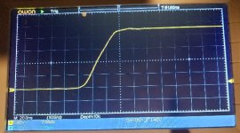
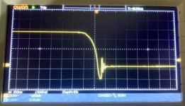
After calibrating the current sensors with a DMM at 10A, I gradually increased the current to 400A. The rising edge is super clean and the falling edge is somewhat acceptable. There was much more change from 0 to 200A than 200 to 400A. The scope readings were taken with a twisted pair connected between drain and source of a low-side FET via a 200MHZ Owon scope.

Edge1.jpg
Rising edge. This is way cleaner than I expected and more than acceptable for 400A.

Edge2.jpg
Falling edge. Not great but not too bad. I'd prefer no avalanche but 20ns of it isn't bad compared to the maximum rating of 200A for 5uS at a junction temp of 100c. Gate resistor tweaking should clean this up.
 
thorlancaster328 said:
After a bit of testing, everything is looking pretty good, except for the current measurement. Turns out that the "12-bit" ADCs in the MCU I am using (IMXRT1062 / Teensy 4.0) have 3 LSBs of noise... with 8x oversampling :( Looks like the next build will need external ADCs to support the high precision drive mode I was planning on doing. Current hardware is now incapable of sensorless from standstill and Hubwoofer will be sub-optimal.
If the new ADCs truly have 12 bits of noise-free resolution (datasheet says they do), the aforementioned features should be more than doable. During early testing, they (kind of) worked, but the amount of noise rendered them useless for actual use on a bike. Right now, I'm stuck doing sensored FOC, which works well enough to ride.

On the other hand, the power stage is working very well. Turns out I was switching a bit too fast... The 4.7Ω gate resistors resulted in horrible ringing when switching currents greater than 50A. After adding RC snubbers (c = a bit over FET Coss, R = chosen to have same impedance at ringing frequency), the ringing has gone down to acceptable levels.

After calibrating the current sensors with a DMM at 10A, I gradually increased the current to 400A. The rising edge is super clean and the falling edge is somewhat acceptable. There was much more change from 0 to 200A than 200 to 400A. The scope readings were taken with a twisted pair connected between drain and source of a low-side FET via a 200MHZ Owon scope.

Edge1.jpg
Rising edge. This is way cleaner than I expected and more than acceptable for 400A.

Edge2.jpg
Falling edge. Not great but not too bad. I'd prefer no avalanche but 20ns of it isn't bad compared to the maximum rating of 200A for 5uS at a junction temp of 100c. Gate resistor tweaking should clean this up.

I know someone who's using that MCU and is able to run sensor less from standstill and sensorless observer from about 300erpm to 300kerpm. He's using the internal ADCs.

Switching underrshoot at 25V seems rather large. Did you follow the normal method for calculating rc snubbers, that is making them such that the damping factor zeta is critical?

Hope your patent is valid and you've found something new/novel. There's not a whole lot left that's patentable in PCB layout...
 
I had rudimentary sensorless from standstill a while back with a Teensy 4. Never got it working really well though. Even if I could get industry-standard FOC working sensorlessly from a standstill, my system has some different components in it compared to standard FOC which enables it to accurately read current down to an amp or two at 500+ kHz. Should make it a snap (hopefully). I'm sorry I can't tell you more, as I've never heard my current implementations discussed (or even hinted at) anywhere.

I'm not sure why the undershoot isn't the same as the overshoot either. I'm using a twisted pair from low-side gate to source and get the same readings if I connect near the high-side FET. I calculated snubbers by letting cSNB = cOSS of 2 parallel FETs and rSNB to equal cSNB at the ringing frequency of the first spike. I probably did that wrong, should have used the higher frequency ringing after the spike to calibrate. I can also try your Z-matching method where you calculate the resonant L from the cOSS.

Regarding the board, I'm pretty certain it's patentable because I'm getting several times the industry-leading current density (Addapto, Nucular, ASI) and if it was already in use the industry-standard current density would be several times higher. I'll be able to post it here once the patent goes through. It could make your MESC much more powerful.
Edit: Grammar
what happened did the patent come through ? are you going to share your board design ?
 
Back
Top