j bjork
1 MW
For those here that dosent read my yamaha thread, I will post basically the same thing as I did there.
I have a CL1400 and a QS180 90h, early model with hall sensors.
There has been problems from the start to get it running properly, and hackey thinks that it all should be solved with changing to encoder instead of hall sensors.
I get that it is better, but I am not convinced that it will solve the issues.
What do you think?
There has 2 problems that I thought were the same or related, but maybe the weren't.
1: The small stutter/hesitation at low speed when it switches from hall sensors to observer.
2: A stutter that stays over the rpm range, a lot of lost power and rough running.
1 was probably solved with some tuning and the beta fw 6.05
2 started the second time I was riding it on a track, I noticed the rough running and went back home.
At home it was gone, and the bike worked normal again.
Around that time we did the switch to 6.05, tuned it a little at home and it seemed fine.
Tested more, after a while the problem 2 came back. It came more often, and now it seems to be constant.
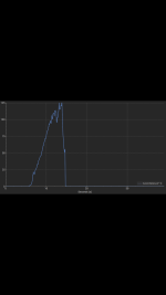
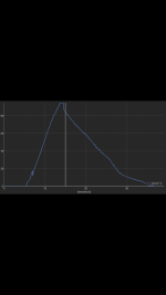
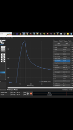
Eventually I tried doing a motor detection again:

The saved values with 2,8mOhm and about 65uH should be about right, 600mOhm etc. not so much..
It looks like it is time to change back to the fardriver, or what do you think?
I have a CL1400 and a QS180 90h, early model with hall sensors.
There has been problems from the start to get it running properly, and hackey thinks that it all should be solved with changing to encoder instead of hall sensors.
I get that it is better, but I am not convinced that it will solve the issues.
What do you think?
There has 2 problems that I thought were the same or related, but maybe the weren't.
1: The small stutter/hesitation at low speed when it switches from hall sensors to observer.
2: A stutter that stays over the rpm range, a lot of lost power and rough running.
1 was probably solved with some tuning and the beta fw 6.05
2 started the second time I was riding it on a track, I noticed the rough running and went back home.
At home it was gone, and the bike worked normal again.
Around that time we did the switch to 6.05, tuned it a little at home and it seemed fine.
Tested more, after a while the problem 2 came back. It came more often, and now it seems to be constant.
Eventually I tried doing a motor detection again:
The saved values with 2,8mOhm and about 65uH should be about right, 600mOhm etc. not so much..
It looks like it is time to change back to the fardriver, or what do you think?