You are using an out of date browser. It may not display this or other websites correctly.
You should upgrade or use an alternative browser.
You should upgrade or use an alternative browser.
1972 Honda CB350F conversion process
- Thread starter rfndzc
- Start date
rfndzc
100 mW
- Joined
- Apr 14, 2020
- Messages
- 49
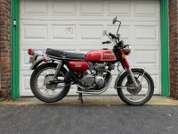
The motorcycle was not running when I picked it up but it was complete, which was important as I wanted to channel the CB aesthetic through the conversion process and starting whole helped guide that:
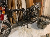
First step was obviously dissasembly:
The design of the battery was almost entirely about solving for three qualities:
The first was I wanted the frame left unmodified, meaning no cuts, no welds to the original CB. That was important to the spirit of the project and I think it's why the bike looks good today, and still projects CB style, despite being an evident conversion. I targeted using the original motor and transmission mounting points, as well as the two existing 10mm bolt holes along the top of the frame for added support.
Next was the need to fit 23 cells to achieve a 72v system (lifepo4 @ 3.2v each = 73.6v). And thirdly, was getting the most torqued up motor I could fit in the remaining space.

First step was obviously dissasembly:

The design of the battery was almost entirely about solving for three qualities:
The first was I wanted the frame left unmodified, meaning no cuts, no welds to the original CB. That was important to the spirit of the project and I think it's why the bike looks good today, and still projects CB style, despite being an evident conversion. I targeted using the original motor and transmission mounting points, as well as the two existing 10mm bolt holes along the top of the frame for added support.
Next was the need to fit 23 cells to achieve a 72v system (lifepo4 @ 3.2v each = 73.6v). And thirdly, was getting the most torqued up motor I could fit in the remaining space.
Last edited:
rfndzc
100 mW
- Joined
- Apr 14, 2020
- Messages
- 49
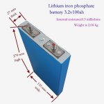
It became clear that if I hoped to achieve 23 cells in the frame they would have to be accommodated laterally, meaning perpendicular to the plane of the frame, with the poles facing out all to one side of the bike. The width of the body (side to side) would accomodate up to about 12" of cell length. Searching through cell options I settled on the one that provided the narrowest end profile I could find (27mm x 135mm) and was the full allowable length (to maximize Ah).
Unfortunately, most of the 72v PMAC motor options I was seeing were too large of radius for the space and too narrow in profile to take advantage of the full volume available. I also would want the motor shaft to sit as close as possible to where the transmission's driveshaft sat on the original bike, to retain the integrity of the drive chain and swing arm movement, but which all added additional constraints to finding a suitable motor. Having the cell and motor specs and with a rough outline of the frame I played around with paper cutouts and could see the motor options were not going to fit.
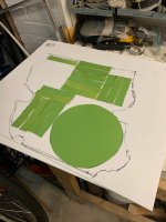
Then I read someone mention an Israeli outfit that was building custom outrunner motors, which is where the stator is wound around the motor shaft and the rotor magnets are affixed to the exterior housing (which turns). As I learned, this makes for a significantly longer torque arm compared to a traditional (inrunner) motor of the same radius. Plus they were fatter to better occupy the full space and offered custom windings for my kV specifications so I could further max out the torque based on what top speed (rpm) I would be willing to cap the machine at (~65mph).
The layout with the outrunner dimensions was tight but just compact enough to fit. Keep in mind the motor fits between the frame so the mounts themselves do not impact the area occupied by the motor.
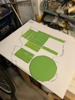

Unfortunately, most of the 72v PMAC motor options I was seeing were too large of radius for the space and too narrow in profile to take advantage of the full volume available. I also would want the motor shaft to sit as close as possible to where the transmission's driveshaft sat on the original bike, to retain the integrity of the drive chain and swing arm movement, but which all added additional constraints to finding a suitable motor. Having the cell and motor specs and with a rough outline of the frame I played around with paper cutouts and could see the motor options were not going to fit.

Then I read someone mention an Israeli outfit that was building custom outrunner motors, which is where the stator is wound around the motor shaft and the rotor magnets are affixed to the exterior housing (which turns). As I learned, this makes for a significantly longer torque arm compared to a traditional (inrunner) motor of the same radius. Plus they were fatter to better occupy the full space and offered custom windings for my kV specifications so I could further max out the torque based on what top speed (rpm) I would be willing to cap the machine at (~65mph).
The layout with the outrunner dimensions was tight but just compact enough to fit. Keep in mind the motor fits between the frame so the mounts themselves do not impact the area occupied by the motor.

rfndzc
100 mW
- Joined
- Apr 14, 2020
- Messages
- 49
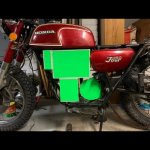
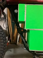
Once I had the anticipated layout I made some mock cells and motor out of foamboard to test fit against the real frame. Not a lot of room for play. Ended up flipping the front bracket upside down which afforded a better fit and support for the cell stack.
Satisfied with the proposed layout, I got started on the battery cage. I began with 1/2" wide steel but quickly realized that was too flimsy and changed to 3/4" wide. I had very little welding experience, as I'm sure it shows, but learned a lot and certainly improved as the build progressed.
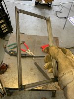
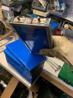
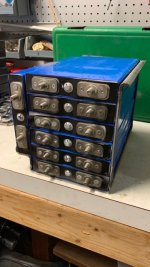
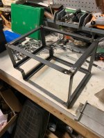
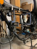
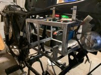


Satisfied with the proposed layout, I got started on the battery cage. I began with 1/2" wide steel but quickly realized that was too flimsy and changed to 3/4" wide. I had very little welding experience, as I'm sure it shows, but learned a lot and certainly improved as the build progressed.


Last edited:
Further pics you've not gotten posted yet may clarify this, but in case they don't: What method of compression plates (thick and stiff enough to ensure equal pressure over their entire area) on each end of every cell stack have you used? Were they clamped with straps or long bolts at the corners, etc?
rfndzc
100 mW
- Joined
- Apr 14, 2020
- Messages
- 49
You're saying to keep the cells from spilling out of the cage?Further pics you've not gotten posted yet may clarify this, but in case they don't: What method of compression plates (thick and stiff enough to ensure equal pressure over their entire area) on each end of every cell stack have you used? Were they clamped with straps or long bolts at the corners, etc?
No, because (regardless of seller claims I've seen) all of these types of cells (non-cylindrical) need this to keep the cells from swelling which degrades them, and/or causes connection issues, etc.
Some usages of such cells don't push them hard enough to cause the swelling, which is good, so if yours don't, then you may not need this.
Cylindrical cells are naturally compressed by the design of their cases, but non-cylindrical cells are designed to be externally compressed, or rather, restrained so that they can't swell (which results in compression as they do swell)...if they can swell it can allow gas buildup in the cell between layers, disconnecting parts of the layers from each other and reducing capacity, etc. Another problem with swelling is it puts strain on the interconnects, and if the interconnects are solidly built the strain is instead passed to the internal connection in the cell between terminal and jellyroll.
For my SB Cruiser, I've got some ancient EIG pouch cells taht aren't compressed, but are slightly restrained by their cell holders secured with packing tape around the entire structure, but I am also not using these cells anywhere near their design limits (not even 1C out of the 5C they were designed to handle, and not charging to full, nor emptying very far most of the time), so I don't see swelling with them (I did have swelling in one cell some time back in a different pack of them, this cell had failed but it's unclear if the swelling caused the failure or was just a symptom of it).
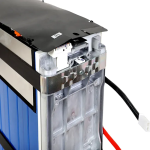
Take a look at this similar cell's battery housing, for an example:
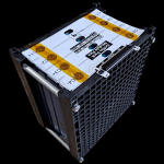
another variation
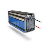
Some usages of such cells don't push them hard enough to cause the swelling, which is good, so if yours don't, then you may not need this.
Cylindrical cells are naturally compressed by the design of their cases, but non-cylindrical cells are designed to be externally compressed, or rather, restrained so that they can't swell (which results in compression as they do swell)...if they can swell it can allow gas buildup in the cell between layers, disconnecting parts of the layers from each other and reducing capacity, etc. Another problem with swelling is it puts strain on the interconnects, and if the interconnects are solidly built the strain is instead passed to the internal connection in the cell between terminal and jellyroll.
For my SB Cruiser, I've got some ancient EIG pouch cells taht aren't compressed, but are slightly restrained by their cell holders secured with packing tape around the entire structure, but I am also not using these cells anywhere near their design limits (not even 1C out of the 5C they were designed to handle, and not charging to full, nor emptying very far most of the time), so I don't see swelling with them (I did have swelling in one cell some time back in a different pack of them, this cell had failed but it's unclear if the swelling caused the failure or was just a symptom of it).
Take a look at this similar cell's battery housing, for an example:

another variation


Last edited:
rfndzc
100 mW
- Joined
- Apr 14, 2020
- Messages
- 49
I see. The cage definitely is quite tight around the cells when installed, particularily toward the ends the cells which is where the pressure from the cage is concentrated, such that there is little or no concern at least of strain on the terminals. There may still be some swelling potentially towards the middle of the cell but wasn't really a consideration when I set out. If I needed to address that I suppose I would add an additional 3/4" bar around the entire cage to reinforce the pressure around the middle of the cells.No, because (regardless of seller claims I've seen) all of these types of cells (non-cylindrical) need this to keep the cells from swelling which degrades them, and/or causes connection issues, etc.
...
If the cage secures the edges of the cells so they can't move away from each other, that will effectively do *almost* what the end plates would, except for the end cells themselves, which will still be able to swell on their outer end faces.
If there's no swelling, it's all good.
But if you do have an issue with swelling in the end cells, a bar across these faces won't fix it; it requires a plate the same dimensions as the large side of the cell, on each end of the cell stack, to apply even pressure across that whole face. (this is what the end cells are in this case doing for all the cells between them).
BTW, the conversion pics and description details are really appreciated--too few people document the process, especially of those that successfully complete a build.
rfndzc
100 mW
- Joined
- Apr 14, 2020
- Messages
- 49
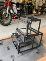
After placing the upper cage where I wanted it (abutting the gas tank above it and as far forward as possible) I could position the lower cage as far towards the front of the frame as this allowed, thereby leaving as much room as possible for the motor behind it. Here were the upper and lower cages before connecting them.
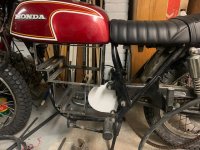
This was connecting the two:
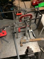
In the course of building this I probably installed and removed the cage and all the cells dozens of times to check the fit. At this point, I checked it again and determined it was ready to add the mounting brackets which would set its final position. Here details of the cage with mounting brackets:
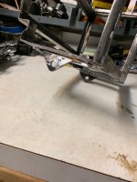
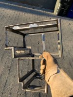
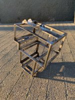
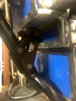
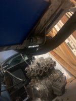
Checking the fit now with the brackets installed and the cage mounted to the frame.
This photo also illustrates the passive retention system for the cells that ensures they stay in place in the cage and are not dependent on the fairing cover for this. You can see along the right side of the cage in this view as well as the middle-left corner, I welded angled bar of the 1/2" stock. That requires that the cells are inserted in a somewhat specific order so as to fit into the cage and slide laterally behind this angled stock. Of the 23 cells, only 5 of them (4 on top, 1 on bottom) are not retained behind the angled stock but are quite secure with the busbars that will tie them to each other, plus the fairing cover and the pressure from adjacent cells.
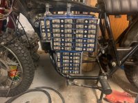
You'll notice the cage is slightly off center, which was intentional to allow for the length of the poles
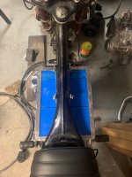
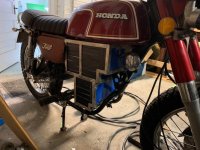

This was connecting the two:

In the course of building this I probably installed and removed the cage and all the cells dozens of times to check the fit. At this point, I checked it again and determined it was ready to add the mounting brackets which would set its final position. Here details of the cage with mounting brackets:


Checking the fit now with the brackets installed and the cage mounted to the frame.
This photo also illustrates the passive retention system for the cells that ensures they stay in place in the cage and are not dependent on the fairing cover for this. You can see along the right side of the cage in this view as well as the middle-left corner, I welded angled bar of the 1/2" stock. That requires that the cells are inserted in a somewhat specific order so as to fit into the cage and slide laterally behind this angled stock. Of the 23 cells, only 5 of them (4 on top, 1 on bottom) are not retained behind the angled stock but are quite secure with the busbars that will tie them to each other, plus the fairing cover and the pressure from adjacent cells.

You'll notice the cage is slightly off center, which was intentional to allow for the length of the poles


Last edited:
rfndzc
100 mW
- Joined
- Apr 14, 2020
- Messages
- 49
At this point I could start hanging the controller in the former place of the airbox under the seat. Again, making use of existing mounts on the frame, crafted the two sides from maybe 20 gauge steel (somewhat flexible). These metal panels would later be where I hung the contactor and some additional electronics, relays, etc. to keep them accesible behind the fiberglass side decals but out of sight.
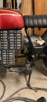
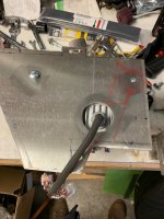
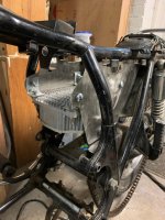
Whereas before, the honda seat would lift up to access the airbox and filter, I now had instead some precious storage space on the motorcycle, which is ideal to store the bike's cover, or any number of other things. Very handy.
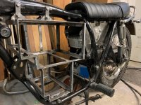


Whereas before, the honda seat would lift up to access the airbox and filter, I now had instead some precious storage space on the motorcycle, which is ideal to store the bike's cover, or any number of other things. Very handy.

Last edited:
SlowCo
1 MW
Awesome conversion. I really like that!
rfndzc
100 mW
- Joined
- Apr 14, 2020
- Messages
- 49
Now that the battery cage position was fixed, I could calculate the dimensions for the motor mounting plate. I dug up the rough measurements from when I was looking at possible motor configurations.
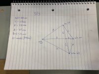
Basic idea:
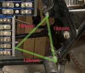
I measured the real distance between the top bolt and bottom bolt and marked these two points on the page. Then found the center of the motor by intersecting the radius of the motor plus a 5mm separation buffer measured from each of the two bolts. I had more flexibility in positioning the third (forward) mount, which would be a bracket welded to the back of the battery cage. As such I decided on an isosceles triangle for a touch of symmetry.
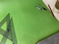
Final dimensions for motor and mount positions:
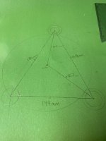
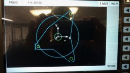
After some back and forth with the machinist we settled on 15mm radius around each bolt center, for material strength. The rest of the shape followed from that, essentially just three triangles centered each on their bolt-motorshaft line, just a minimalist but supremely functional design that conveys elegance in my opinion. Here's the pic the machinist sent from the CNC, I liked the forward cant on it:
Machinist did a great job, beveled edges were unprompted but a really nice touch. Cut from 3/8" aluminum plate:
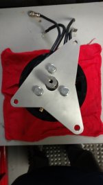
Quickly realized the bolts interfered with the cog and would later have him countersink the bolt holes for a flush fit:
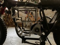

Basic idea:

I measured the real distance between the top bolt and bottom bolt and marked these two points on the page. Then found the center of the motor by intersecting the radius of the motor plus a 5mm separation buffer measured from each of the two bolts. I had more flexibility in positioning the third (forward) mount, which would be a bracket welded to the back of the battery cage. As such I decided on an isosceles triangle for a touch of symmetry.

Final dimensions for motor and mount positions:

After some back and forth with the machinist we settled on 15mm radius around each bolt center, for material strength. The rest of the shape followed from that, essentially just three triangles centered each on their bolt-motorshaft line, just a minimalist but supremely functional design that conveys elegance in my opinion. Here's the pic the machinist sent from the CNC, I liked the forward cant on it:

Machinist did a great job, beveled edges were unprompted but a really nice touch. Cut from 3/8" aluminum plate:

Quickly realized the bolts interfered with the cog and would later have him countersink the bolt holes for a flush fit:


