Following you closely! Looking to do a similar build with my wife's small frame. Do you have a side door on both sides (engine and battery box)? I kinda want a little more distance out of it and around 65mph top speed I want to try for somewhere around 72v 60ah with a qs212 7kw motor. I'm just not sure where to put all the batteries. I might just hack up the area under the seat to make more space.
You are using an out of date browser. It may not display this or other websites correctly.
You should upgrade or use an alternative browser.
You should upgrade or use an alternative browser.
1974 Vespa 125 Primavera conversion, 5kw hub motor
- Thread starter Voltspa
- Start date
kingkongshrimp
10 W
- Joined
- Nov 2, 2021
- Messages
- 72
I just finished my build for my 1957 Lambretta.
https://endless-sphere.com/forums/viewtopic.php?p=1684953#p1684953
Got lot's of help from my friends "Resistor" over at ModernVespa.
Here's his build
https://modernvespa.com/forum/topic163759?highlight=
https://endless-sphere.com/forums/viewtopic.php?p=1684953#p1684953
Got lot's of help from my friends "Resistor" over at ModernVespa.
Here's his build
https://modernvespa.com/forum/topic163759?highlight=
Voltspa
100 mW
- Joined
- May 2, 2021
- Messages
- 42
It's been so long I just had to re-read my thread as if it was somebody else's 
I have been slowly making progress on the battery. I ended up settling on a 200A Daly BMS. It is huge! any bigger and it wouldn't fit in my battery pan(s). I am going to attempt to make some updates and post some pics.
I have been slowly making progress on the battery. I ended up settling on a 200A Daly BMS. It is huge! any bigger and it wouldn't fit in my battery pan(s). I am going to attempt to make some updates and post some pics.
Voltspa
100 mW
- Joined
- May 2, 2021
- Messages
- 42
Willwarn said:Following you closely! Looking to do a similar build with my wife's small frame. Do you have a side door on both sides (engine and battery box)? I kinda want a little more distance out of it and around 65mph top speed I want to try for somewhere around 72v 60ah with a qs212 7kw motor. I'm just not sure where to put all the batteries. I might just hack up the area under the seat to make more space.
Willwarn,
60ah is quite a goal with a small frame but you can get creative! luggage racks (front or rear) or under the seat, as in inside the seat, maybe?
And wow, in the time I've been working on this, QS has released a 7kw 10" hub motor! I had no idea....
Make sure that will even fit in a small frame...it'll be tight! Keep us posted!
Voltspa
100 mW
- Joined
- May 2, 2021
- Messages
- 42
kingkongshrimp said:I just finished my build for my 1957 Lambretta.
https://endless-sphere.com/forums/viewtopic.php?p=1684953#p1684953
Got lot's of help from my friends "Resistor" over at ModernVespa.
Here's his build
https://modernvespa.com/forum/topic163759?highlight=
Kingkong (may I call you kingkong?),
Yes! I followed your project with awe. I wish I could be so focused on mine. I will get there eventually. Thank you for sharing yours, it is a gem!
Voltspa
100 mW
- Joined
- May 2, 2021
- Messages
- 42
amberwolf said:I like the idea of keeping it's patina; makes me think of Reki's scooter (everything the Haibane have or use was someone else's used / discarded stuff):
op-07[1].jpg
IMG_2662[1].jpg
Amberwolf,
I love old things. Unfortunately a lot of that patina just rubs off, but don't worry I wont be buffing it anytime soon.
Voltspa
100 mW
- Joined
- May 2, 2021
- Messages
- 42
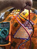
series connections made using the copper sandwich method. 0.15mm copper and 0.10 nickel plated steel. 110J with a Kweld and a tractor battery.
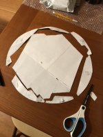
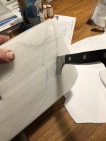
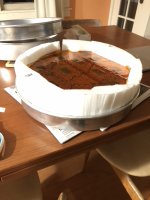
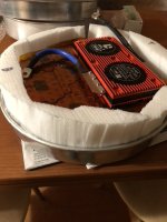
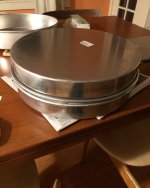
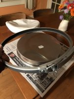
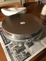
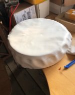
Two 2" cake pans clamped together with a duct clamp is the final design for my fake spare tire battery. Looks more like a drum than a tire but I'll see what I can do...
look at the size of that BMS! but it fits.
Voltspa
100 mW
- Joined
- May 2, 2021
- Messages
- 42
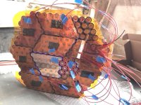
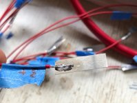
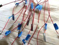
Figuring out the BMS signal wires, soldering on tabs to spot weld to the parallel groups.
Now I am at the point that I need to attach these 2AWG BMS wires to the battery. The 0.15 cooper will be my bus bar. On the #0 negative and the #20 positive, I will leave enough copper that I can curl it around a pre-tinned 2AWG end and solder it before spot welding to the battery.
A thought about the BMS: The heatsink has fans in it. This implies it is designed such that it will get very hot in use. The fans are there to pull cool air from an outside source over the heatsink to pull heat out of it and send it somewhere else.
If there is no where for the heat to go, then if heat buildup inside the BMS does not either trigger it's thermal shutdown (if it has one, and if it's properly implemented) or fail from componenent overheating, then it will heat the cells up until they are as hot as the BMS, and if nothing happens to stop the process, that heat will increase until the usage stops for whatever reason so that the BMS is no longer generating heat.
What the heat does to the cells depends on the cell model/etc., and how hot they get and how long they stay that way.
What it does to the BMS depends on how hot and how long, but usually it damages teh FETs, and they often fail shorted, meaning stuck on, so that the BMS cannot turn off charge or discharge even under conditions that can damage the cells.
If there is a way to install the BMS heatsink into a hole in the casing such that the fans and fins are all outside the casing, that will minimize the above potential problem. You would need to seal around the edges of the heatsink where it mates with the casing, to ensure no environmental intrusion into the BMS or cell area, though.
The back heatsink is still inside with the cells, however, and will keep pushing heat into the pack. I don't see an simple, easy way to deal with that.
If the "spare tire" is mounted so the BMS faces the fairing, it won't be visible and spoil the look.
If you like you can test the system as-is and then see if temperatures ever get high enough to require the modification, before changing anything.
Side note: if that is a Daly BMS, you may wish to check out Methods' thread(s) on them. Since it's a different version it may not have the same vulnerabilities, but worth knowing about. .
Voltspa
100 mW
- Joined
- May 2, 2021
- Messages
- 42
Thanks Amberwolf. As far as I can tell those fan-looking plates are just decorative, though it's clear that they expect it to produce heat, as the whole casing has heat sink fins, but it looks like those things are just glued on, I don't see any openings under them.
I'm counting on the copper to run cooler and also act as a distributor of heat, as it is an excellent conductor of heat as well as current. I'll put the temperature probe between the BMS and battery to get a good read of the likely hottest spot. I'm going to go forward with this design with caution.
Can you post a link to Methods' threads about Daly? Thanks!
Voltspa
100 mW
- Joined
- May 2, 2021
- Messages
- 42
Soldering on the tabs I made a big mistake... I didn't turn down the power on the Kweld from 110J. I was welding to spots between the batteries and whomp I felt the electrodes go right through the copper. A brief period of sparking luckily ended on its own. I realized that in my haste and excitement to get the last of the series connections made before the ends, I hadn't even put down the extra insulator rings on the cells. The welder had melted through the plastic right to the negative side of two cells! I feel like this could have been worse!
I did some tests with the Kweld power level and found that 25J will do just fine to get the tabs connected to the copper, which is all that needs to be done. Disaster averted I guess.
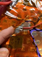
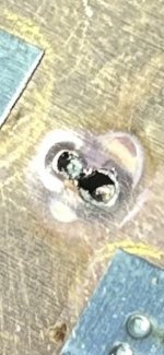
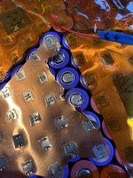
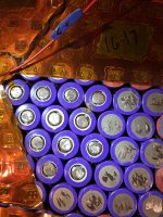
I did some tests with the Kweld power level and found that 25J will do just fine to get the tabs connected to the copper, which is all that needs to be done. Disaster averted I guess.


Dunno if it's possible at this point, but you probably should put those spacer rings on all the positive cell ends, just to prevent the slim possibility of an event while riding from sufficient deformation of the plastic wrap allowing a short like that.
This is one of the threads Methods posted some info/results/etc to:
https://endless-sphere.com/forums/viewtopic.php?t=110087
This is more detailed
https://endless-sphere.com/forums/viewtopic.php?f=14&t=118344
Here's a couple where he is researching a replacement BMS
https://endless-sphere.com/forums/viewtopic.php?f=14&t=118470
https://endless-sphere.com/forums/viewtopic.php?f=14&t=118446
If the covers for the fan recesses are just decorative, I recommend removing them if possible, as it will increase the ability of hte heatsink to shed heat, instead of helping to retain heat in the areas underneath them.
If it's practical I'd still recommend (assuming significant heat out of the BMS) exposing the heatsink to the outside air. If there's no significant heat, then no need to worry, but...
Voltspa
100 mW
- Joined
- May 2, 2021
- Messages
- 42
Amberwolf,
Yes, I put the extra insulator rings on every group but that one, like I said I was excited to be almost done with that step that I spaced out on it!
I value your concern about the heat. It is definitely something I have always seen as a possible weak point of my design. At the very least, the "fan" side of the BMS will be against the aluminum of the pan and I could even apply some additional heat sink on the outside of the pan to help.
I am not building this as a drag racer, so I don't expect to be constantly pushing the limits of the BMS. Others have pointed out that my motor will draw max amps of less than my battery capacity anyway, so I may have chosen a larger BMS than I really need. I will proceed with caution!
Voltspa
100 mW
- Joined
- May 2, 2021
- Messages
- 42
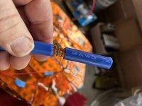
Wrapping the wire as I remove the insulation so it doesn't expand.
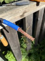
Ready to pre-tin.I used a propane blow torch.
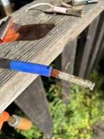
Took off the wire as it was cooling.
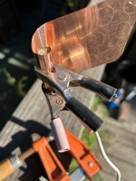
Ready to solder on the copper of the negative end before spot welding to the cells.
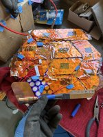
Ready to spot weld.
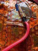
The positive end done!
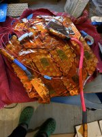
Ready to connect the BMS.
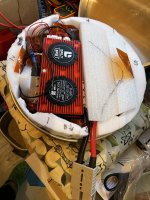
Oh lawd, it fits!
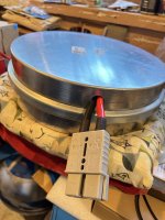
I know I need a grommet for this situation!
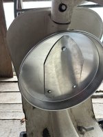
I used a piece of stainless steel as reinforcement, like a giant washer, and carriage bolts to wingnuts with lock washers. It feels pretty solid when all put together.
Voltspa
100 mW
- Joined
- May 2, 2021
- Messages
- 42
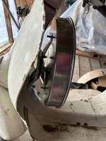
Here's a side view, wingnuts not on yet.
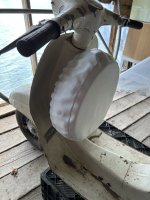
Whole battery with cover on.
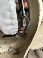
I need to drill a hole into the center channel to connect the batt.
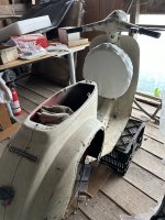
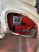
Looks like I can fit the charger, inverter, and fuse box in the old battery compartment. The controller, contactor, and circuit breaker should easily fit under the seat.
Keep in mind the controller is designed to get airflow over it's heatsink to keep it cool. If it doesn't have that, it could overheat. Same thing for the DC-DC and charger.Looks like I can fit the charger, inverter, and fuse box in the old battery compartment. The controller, contactor, and circuit breaker should easily fit under the seat.
If the charger has it's own fan it just needs air from outside the compartment ducted to the charger's air intake (and a separate duct from it's outlet to the outside unless the compartment has venting).
But the DC-DC you should check how hot it gets in an enclosed space with no airflow under the maximum load it will ever see continuously, before sealing it away.
I'd do that with the controller, too, if possible--at least put a temperature sensor in there with it to monitor manually, if you don't have something that logs it for you, then go ride hard and see what it gets to, in case it's hot enough to require ventilation/etc.
From-A-To-B
100 W
It looks like it's coming along nicely, Voltspa. Getting all the copper spot welding lined up can be a real pain. I'm actually surprised that you only made one spot-welding mistake on the whole build -- well done! Props to Amberwolf for raising all the flags about heat. I also generally subscribe to the idea that anything with heat sink fins or a fan should not be put in a sealed box -- but if you're running everything far below its max duty cycle, maybe things will stay cool for you. I imagine you got this bit tucked away - but I hope there's more than some Kapton tape insulating your beautiful battery build from the metal case of your BMS.
Keep the updates coming!
Keep the updates coming!
Voltspa
100 mW
- Joined
- May 2, 2021
- Messages
- 42
Thanks!It looks like it's coming along nicely, Voltspa. Getting all the copper spot welding lined up can be a real pain. I'm actually surprised that you only made one spot-welding mistake on the whole build -- well done! Props to Amberwolf for raising all the flags about heat. I also generally subscribe to the idea that anything with heat sink fins or a fan should not be put in a sealed box -- but if you're running everything far below its max duty cycle, maybe things will stay cool for you. I imagine you got this bit tucked away - but I hope there's more than some Kapton tape insulating your beautiful battery build from the metal case of your BMS.
Keep the updates coming!
I will surely keep an eye out for things heating up once I get everything connected. I appreciate the feedback. It's why I am here. You all have way more experience than me and I thank you for your words.
In the battery build I used a thin HDPE material in several layers on the bottom of the pan (not pictured) and I will place a couple layers of that between the cells and the BMS too.
From-A-To-B
100 W
That’ll be plenty! Seeing people keep potential voltage differences held back with thin plastic film alone gives me the heebie jeebies. A layer of actual plastic sheet will do the trick.Thanks!
I will surely keep an eye out for things heating up once I get everything connected. I appreciate the feedback. It's why I am here. You all have way more experience than me and I thank you for your words.
In the battery build I used a thin HDPE material in several layers on the bottom of the pan (not pictured) and I will place a couple layers of that between the cells and the BMS too.
Voltspa
100 mW
- Joined
- May 2, 2021
- Messages
- 42
Well THAT was a long pause!*
I need help with connecting a Kelly controller. I have the system powered up (on bench) and my tablet says it's paired, but the app keeps saying to pair the device. So I tried connecting with the cable provided, and still the app says "failed to open device"! I tried deleting and re-installing the app, but still no dice. Anyone?
*After a very busy Fall, I finally got the last few components I needed (contactor, disconnect, power gauge with shunt, various connectors) to do a bench hookup of everything. I really think if I can see the motor turn it will motivate me to find time to get some serious progress done on this. I got it hooked up, flipped the switch, the contactor clicked, nothing blew up, and the bluetooth dongle had a blinking red light. So now I am stuck, not able to run the configuration program. Thanks for any help!
Voltspa
100 mW
- Joined
- May 2, 2021
- Messages
- 42
Updates:
A surge of progress in the last couple months!
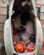
Started installing the components on the bike, finding that I have ample room actually. There will still be room to put the tool bucket back in there!
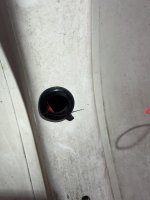
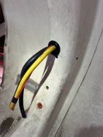
Made the hole and fished the cables through to connect the battery.
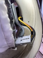
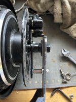
Got a swingarm from Bernie, needed some work to understand how he designed it and a little grinding for cleanup. The 5kw QS motor is much wider than the 3 or 4kw, so he made it wider on both sides to be sure the wheel is centered.
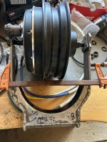
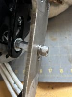
I had to get some hardware to secure the brake torque arm to the swingarm and am pleased with my solution.
I finally got the controller connected by using the provided cable and connecting to my son's gaming computer, which meant bringing the whole setup into his room! Fast forward to now and I've got a tablet running Android 12 and I again can't open the programming software. Kelly now has two options for android, "old" and "new" and neither of them are working for me by cable connection. I think I need to get a new bluetooth dongle as I have the old version, maybe that's the ticket but then I spend more on shipping than the thing costs.
A surge of progress in the last couple months!
Started installing the components on the bike, finding that I have ample room actually. There will still be room to put the tool bucket back in there!

Made the hole and fished the cables through to connect the battery.


Got a swingarm from Bernie, needed some work to understand how he designed it and a little grinding for cleanup. The 5kw QS motor is much wider than the 3 or 4kw, so he made it wider on both sides to be sure the wheel is centered.

I had to get some hardware to secure the brake torque arm to the swingarm and am pleased with my solution.


I finally got the controller connected by using the provided cable and connecting to my son's gaming computer, which meant bringing the whole setup into his room! Fast forward to now and I've got a tablet running Android 12 and I again can't open the programming software. Kelly now has two options for android, "old" and "new" and neither of them are working for me by cable connection. I think I need to get a new bluetooth dongle as I have the old version, maybe that's the ticket but then I spend more on shipping than the thing costs.
Similar threads
- Replies
- 18
- Views
- 1,254
- Replies
- 16
- Views
- 1,866
- Replies
- 3
- Views
- 468
- Replies
- 0
- Views
- 298
- Replies
- 9
- Views
- 1,324


![op-07[1].jpg op-07[1].jpg](https://endless-sphere.com/sphere/data/attachments/187/187824-558d1fc130657491cfa1e717299b110b.jpg)
![IMG_2662[1].jpg IMG_2662[1].jpg](https://endless-sphere.com/sphere/data/attachments/187/187825-3a5be60b087b9777d4c26b0c83cdd36e.jpg)
