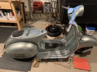
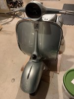
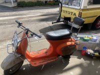
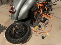
Hello! I’m starting this thread to share details of my conversion build of a 1960 Vespa 150 VBA1T. This project first started as a restoration, but I decided I didn’t want the maintenance of a gas engine. The goal of the project is to preserve the beauty of the original design, but marry with the modern convenience (and hopefully longer term sustainability) of an electric engine.
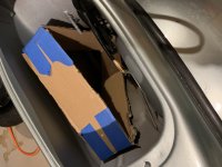
I started with the conversion kit from AliExpress, which included:
QS 72v 2000w hubmotor 10”
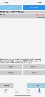
Fardriver controller
12v DC converter
Electronic throttle and battery indicator
I also bought a new wiring loom from SIP scootershop to clean up the original wiring and upgrade to 12v.
After the kit arrived, I realized after it arrived that my scoot per doesn’t have an opening on the handlebars anywhere for the electronic throttle wiring, and I didn’t want to drill holes in the frame, so I needed another solution. I opted for the Sur-Ron analog-to-digital throttle adapter, and a generic keyless starter system from Amazon. Will have to find a solution for a battery indicator though. Thinking I can put a hardwired indicator in the glove box, or hopefully I can find a battery with a Bluetooth BMS and I can just use my phone while riding.
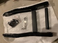
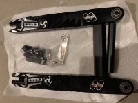
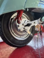
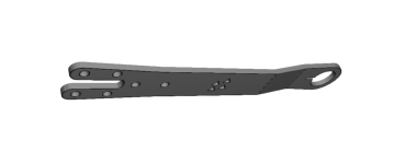
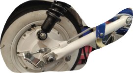
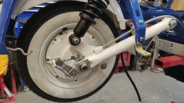
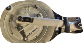
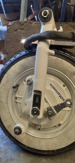
I was stuck on the swingarm for a long time - welding isn’t part of my skill set and I couldn’t find any local fabricators that were willing to take the project on (at least not in a way that was cost-effective). I finally lucked out and found an off-the-shelf swingarm on AliExpress that looks like it will be almost an exact fit for the frame and hub motor. Fingers crossed! The only thing that doesn’t look like it will work out of the box is the placement of the shock mount, so I will have to figure out a plan for that. Hoping I can find some sort of bracket or extension that I can attach that will work? Any thoughts or advice on this appreciated!
Still working on sourcing a battery! Suggestions appreciated on this also.
A few pictures attached.
I started with the conversion kit from AliExpress, which included:
QS 72v 2000w hubmotor 10”
Fardriver controller
12v DC converter
Electronic throttle and battery indicator
I also bought a new wiring loom from SIP scootershop to clean up the original wiring and upgrade to 12v.
After the kit arrived, I realized after it arrived that my scoot per doesn’t have an opening on the handlebars anywhere for the electronic throttle wiring, and I didn’t want to drill holes in the frame, so I needed another solution. I opted for the Sur-Ron analog-to-digital throttle adapter, and a generic keyless starter system from Amazon. Will have to find a solution for a battery indicator though. Thinking I can put a hardwired indicator in the glove box, or hopefully I can find a battery with a Bluetooth BMS and I can just use my phone while riding.
I was stuck on the swingarm for a long time - welding isn’t part of my skill set and I couldn’t find any local fabricators that were willing to take the project on (at least not in a way that was cost-effective). I finally lucked out and found an off-the-shelf swingarm on AliExpress that looks like it will be almost an exact fit for the frame and hub motor. Fingers crossed! The only thing that doesn’t look like it will work out of the box is the placement of the shock mount, so I will have to figure out a plan for that. Hoping I can find some sort of bracket or extension that I can attach that will work? Any thoughts or advice on this appreciated!
Still working on sourcing a battery! Suggestions appreciated on this also.
A few pictures attached.