
You are using an out of date browser. It may not display this or other websites correctly.
You should upgrade or use an alternative browser.
You should upgrade or use an alternative browser.
1987 Yamaha FZR250
- Thread starter soyachips
- Start date
OK so I just used a multimeter to test the voltage on the tabs and also where the wires connect to the PCB board and there’s a 0.3-0.4V difference when discharging the cell but they’re the same at rest. Any ideas what’s going on or how to fix it?
It’s only a $50 device so maybe that’s my problem
I may not be able to measure the actual capacity but hopefully I can I still use the results to pair the cells into 2p groups. Better than nothing I guess!
It’s only a $50 device so maybe that’s my problem
I may not be able to measure the actual capacity but hopefully I can I still use the results to pair the cells into 2p groups. Better than nothing I guess!
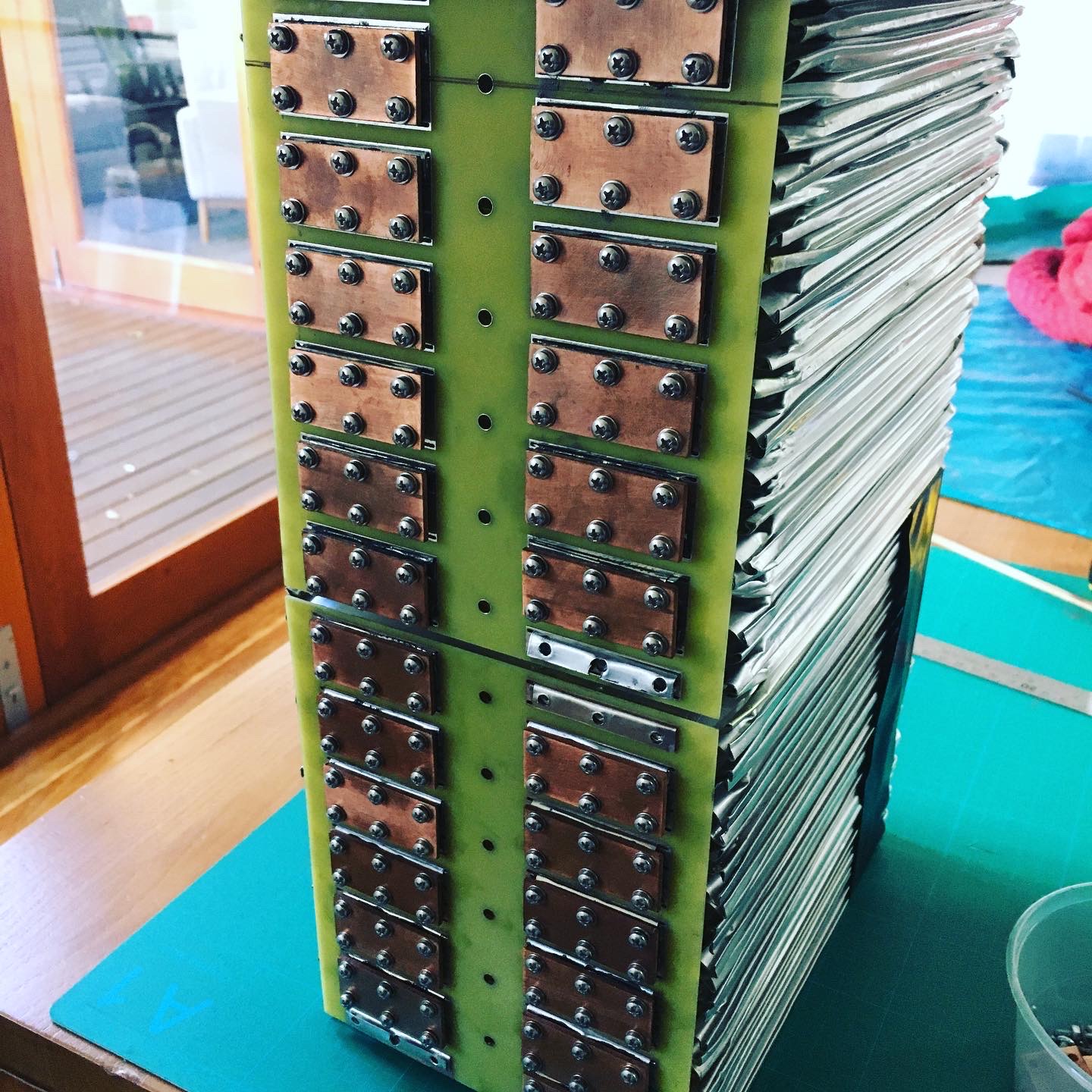
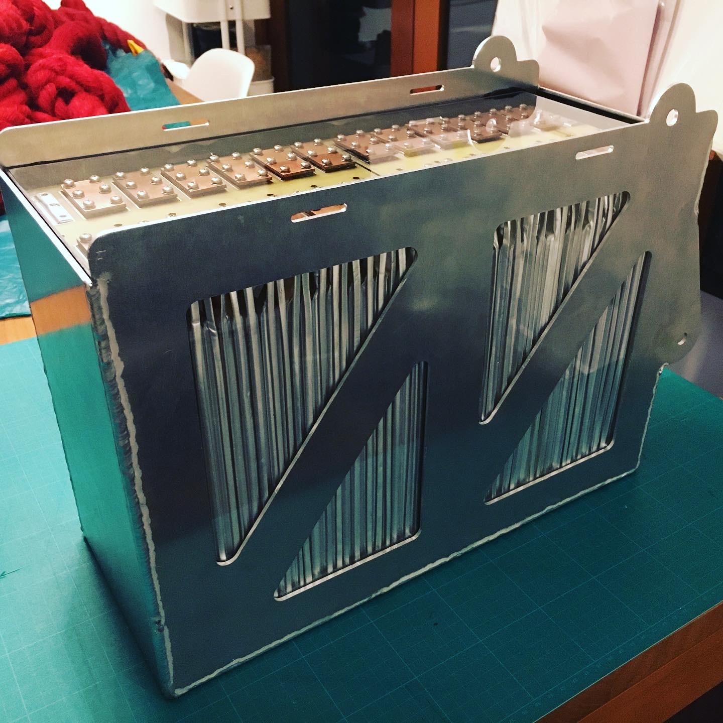
OK so once again its been way too long between posts so I'll add some photos to try and fill the gap up to where the project is now!
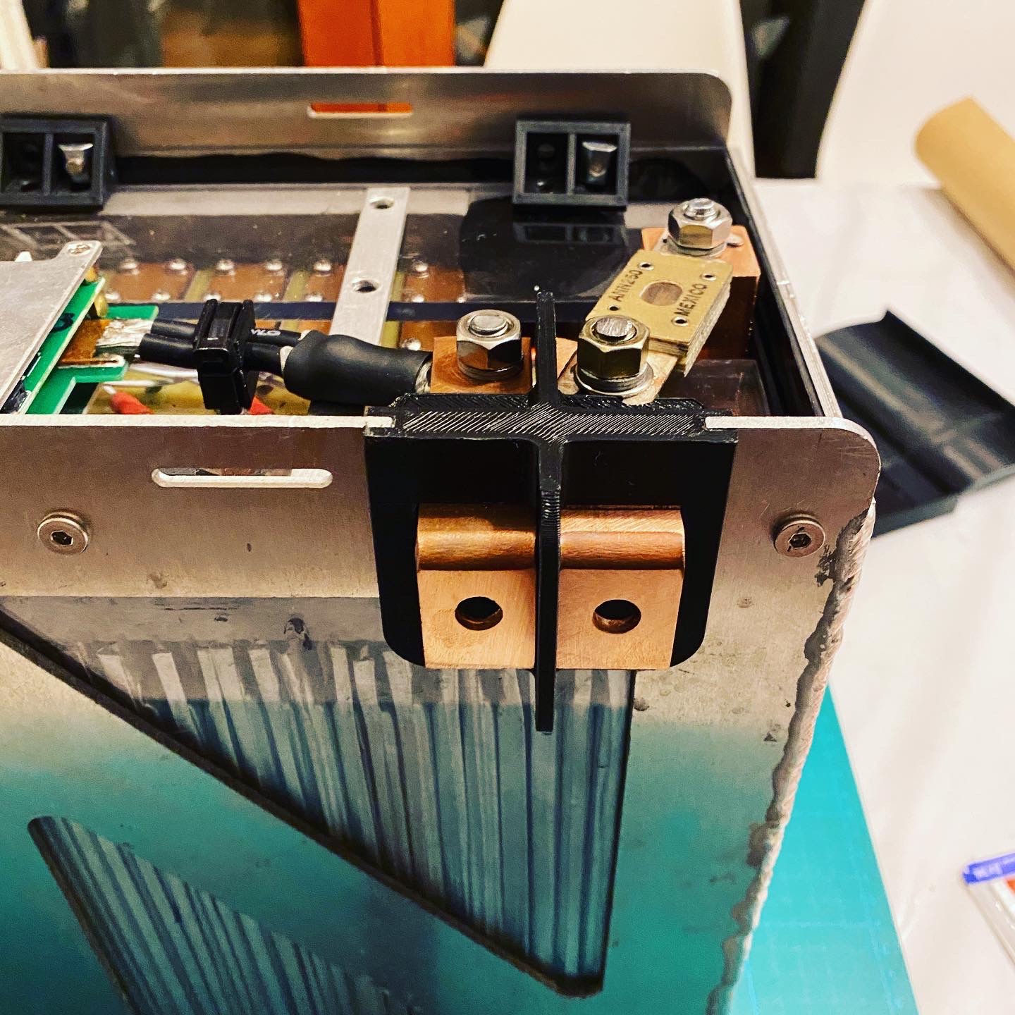
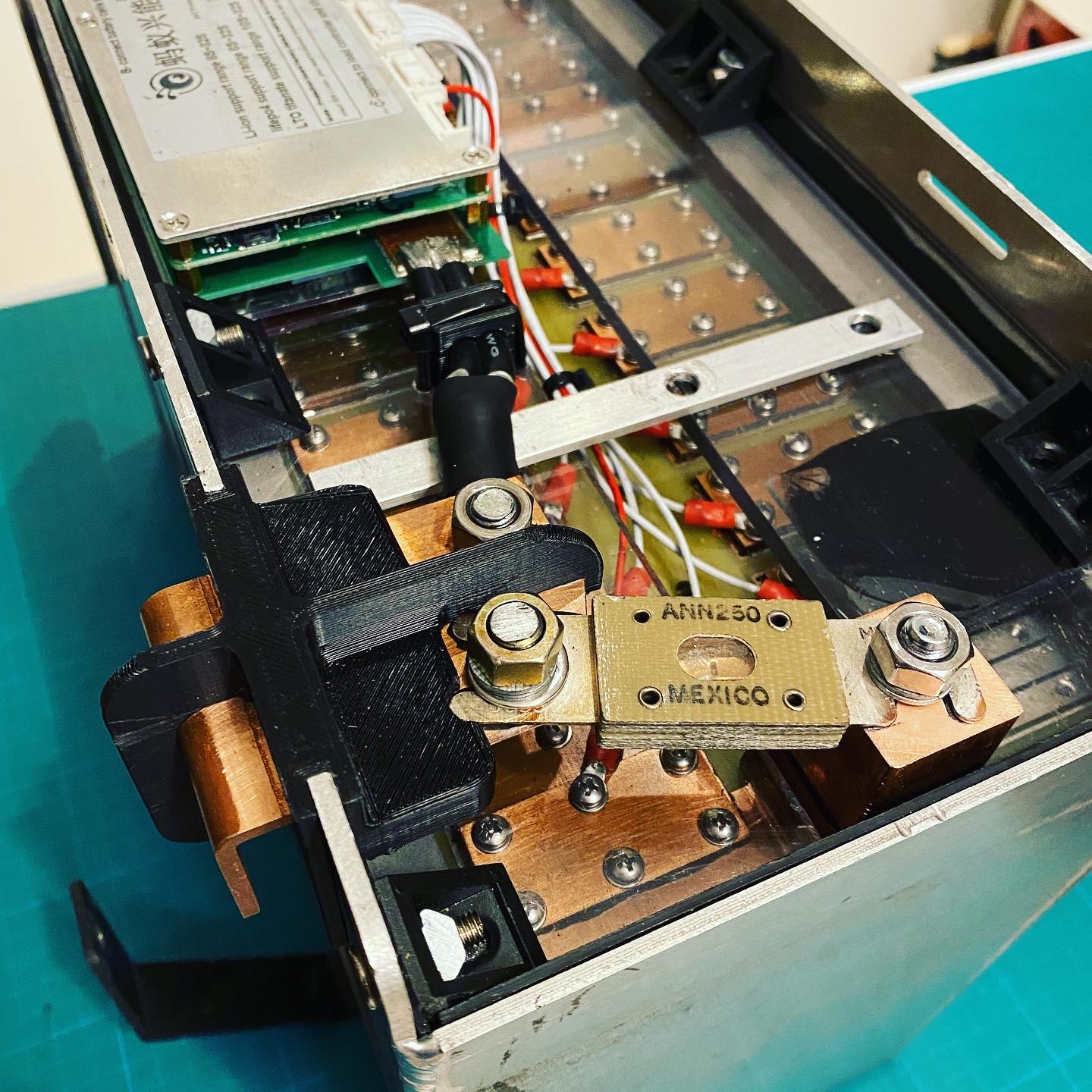
After sorting out the testing I used a fantastic 2p busbar kit made by Chris Jones which made assembly really easy. The panels for the box were cut on a friends CNC router and welded by someone I found on Gumtree (not there yet with my welding skills) and the terminals were made with copper bar and a 3D printed bracket.
After sorting out the testing I used a fantastic 2p busbar kit made by Chris Jones which made assembly really easy. The panels for the box were cut on a friends CNC router and welded by someone I found on Gumtree (not there yet with my welding skills) and the terminals were made with copper bar and a 3D printed bracket.
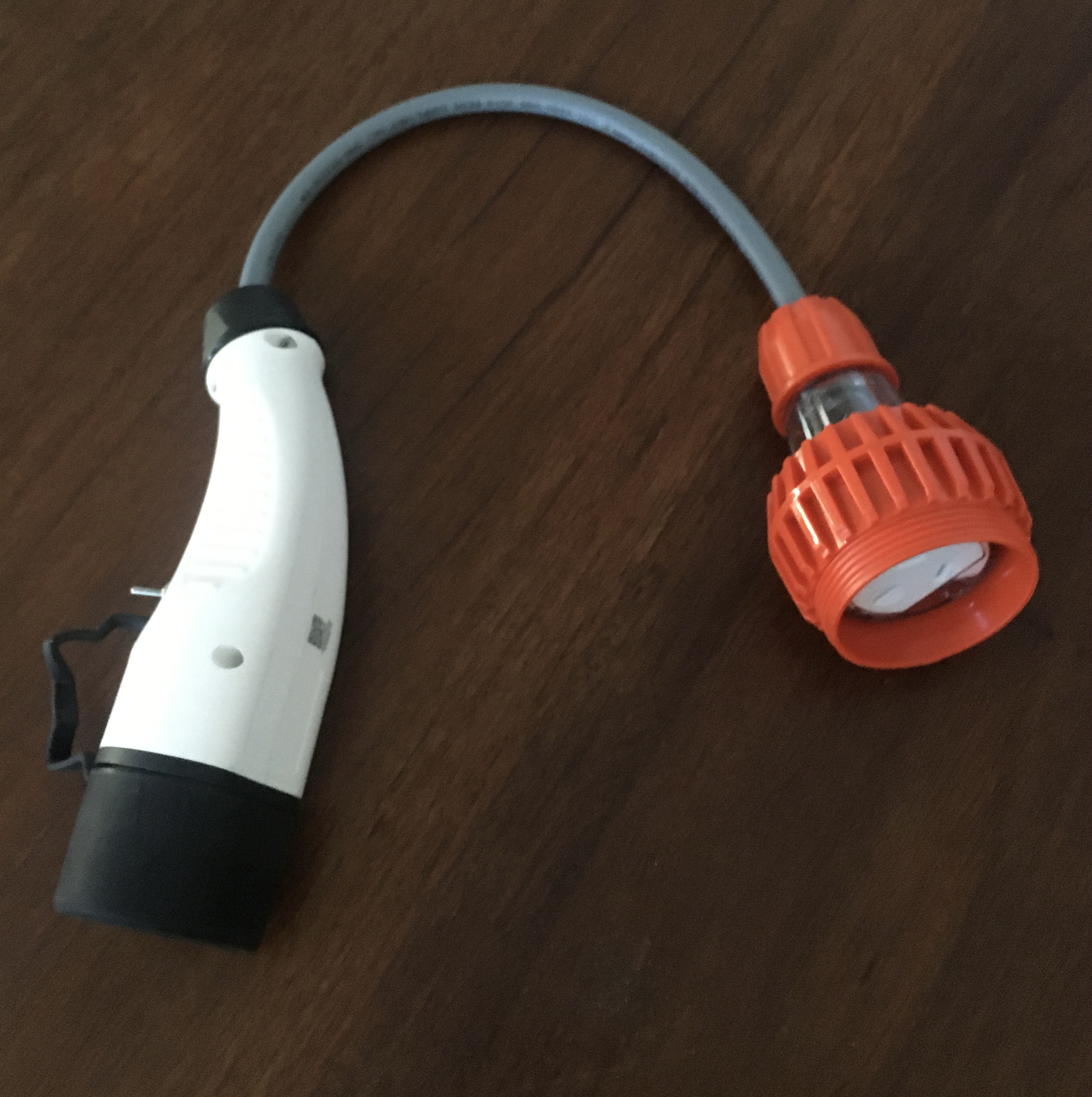
I also discovered the TeslAnything Adapter from EVolution that allows non-Tesla EVs to use their destination chargers and other Type 2 charge points. This paired with a faster charger setup meant I could explore a bit more.
https://electriccarcharger.com.au/p...ing-adaptor-to-bmw-i3-nissan-leaf-ioniq-phev/
https://electriccarcharger.com.au/p...ing-adaptor-to-bmw-i3-nissan-leaf-ioniq-phev/
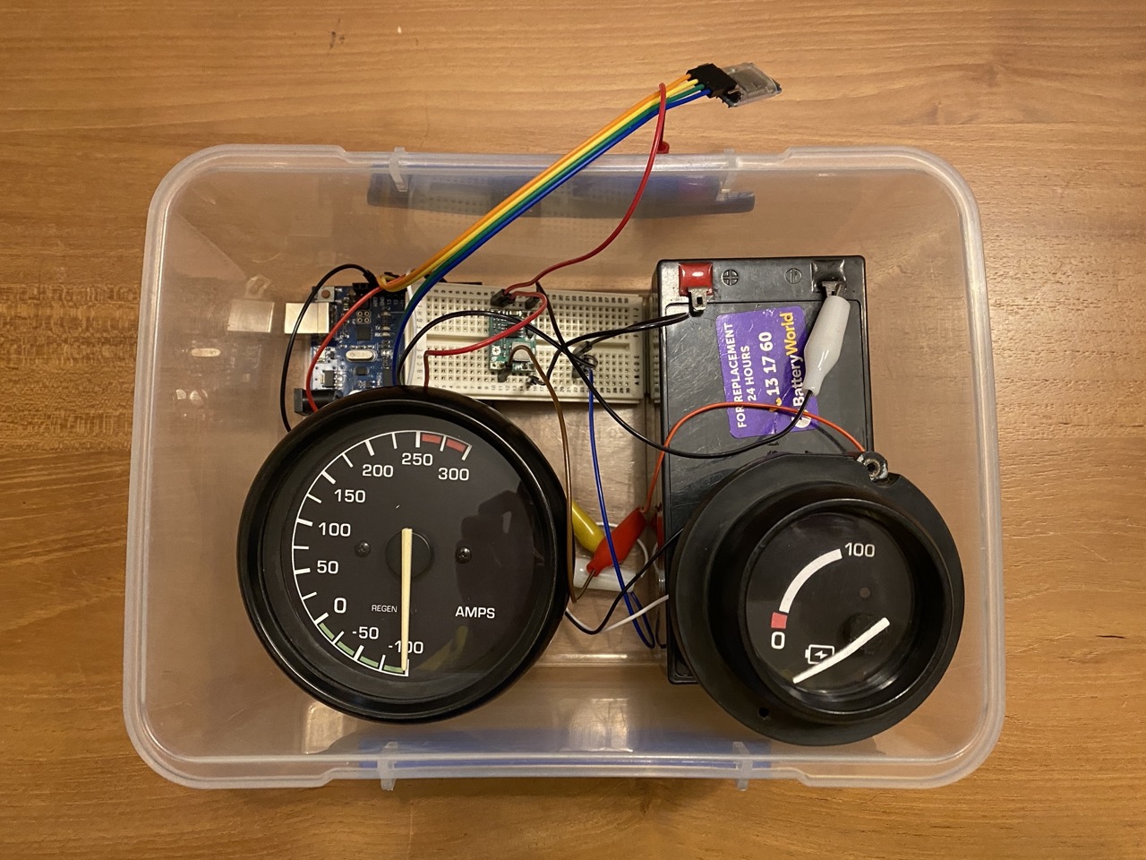
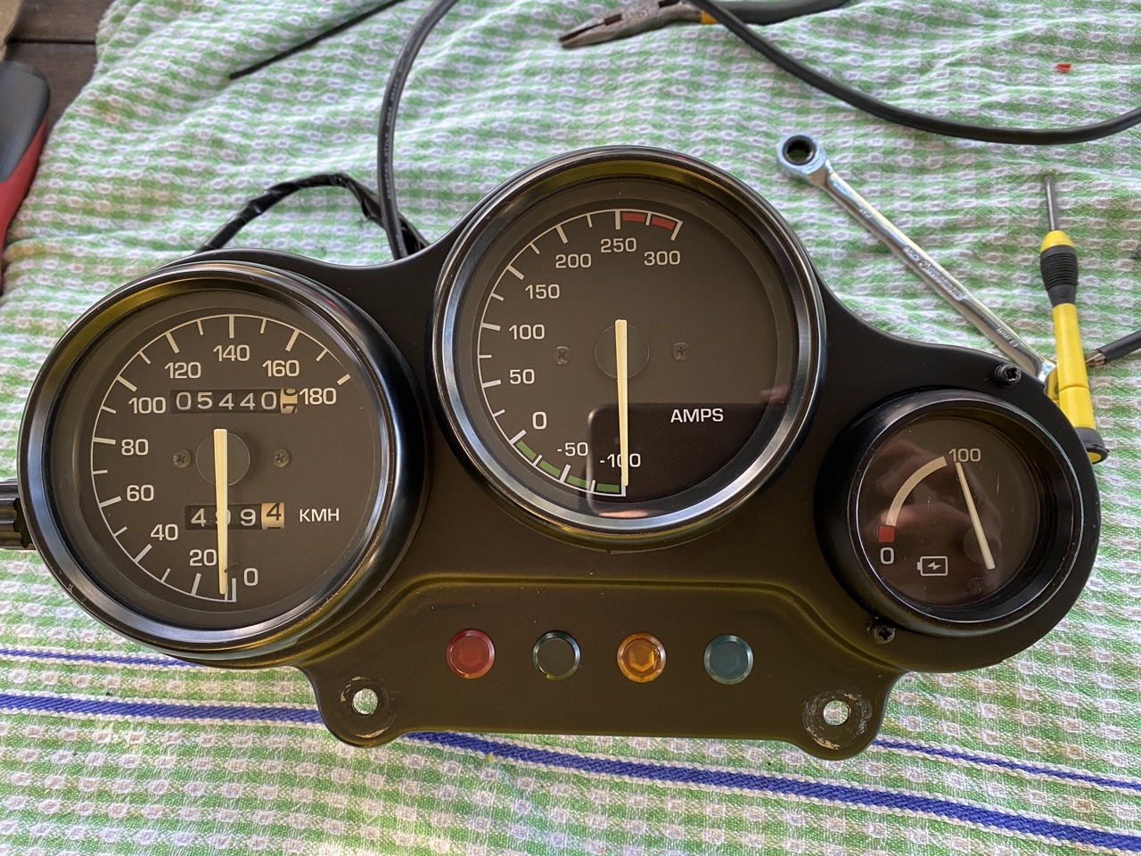
I also started playing around with reading the current and battery SoC out of the ANT BMS and using an Arduino to drive the original gauges but unfortunately never got it working properly. I found an eBay seller that can make custom faces with the proper backlighting for a reasonable price too. Hopefully will get these working soon!
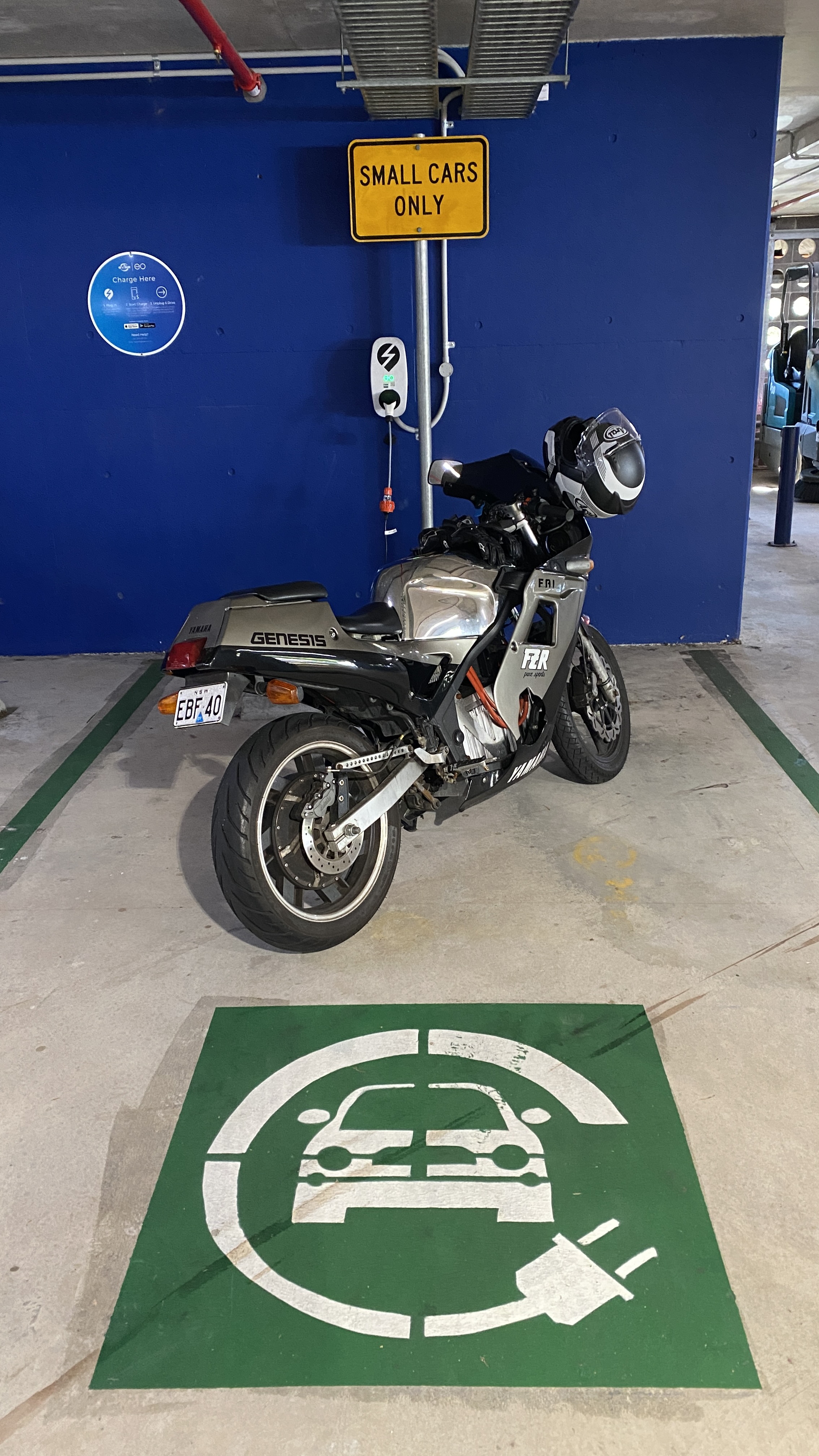
So the battery is now 23s mainly because the controller can only handle 90V. At some point I'll upgrade and go to 26s. Max speed is now 110kmh and range is 150-200km (to be verified). Next step is to replace the DC-DC converter as I've now gone up in voltage a bit above what it's rated for and a new charger that the BMS can control over CAN.
I did a bit of research into CCS charging but that starts at 200V and I'll only be up to 110V once I'm done. Would have been nice though as the only time I'll need to charge now is when I'm going on longer rides on the weekend with friends and I/they don't want to be waiting around for more than a lunch break!
I did a bit of research into CCS charging but that starts at 200V and I'll only be up to 110V once I'm done. Would have been nice though as the only time I'll need to charge now is when I'm going on longer rides on the weekend with friends and I/they don't want to be waiting around for more than a lunch break!
SafeDiscDancing
10 kW
- Joined
- Jan 3, 2022
- Messages
- 514
Great build.
I like how you slowly adapted and overcame obstacles along the way.
That's persistence.
Some see these hobbies as a "get it done in a hurry" thing which I think ruins it because the fun is thinking things through and inventing better solutions as you go.
Your most recent build level at 150 - 200km is very impressive.
SafeDiscDancing said:Great build ...
Thanks, it's been quite a journey but heaps of fun. I finally feel like the bike is good enough to just ride without worrying about things failing and you're a test pilot! I really hope I didn't just jinx myself :lol:
SafeDiscDancing
10 kW
- Joined
- Jan 3, 2022
- Messages
- 514
soyachips said:Thanks, it's been quite a journey but heaps of fun.
I looked up those battery cells on Alibaba and they say they are of the LiFePO4 type but then when listing maximum charge voltage say 4.2 volts.
Isn't the normal maximum for LiFePO4 more like 3.6 volts?
Which value are you using?
SafeDiscDancing said:I looked up those battery cells on Alibaba and they say they are of the LiFePO4 type but then when listing maximum charge voltage say 4.2 volts.
Isn't the normal maximum for LiFePO4 more like 3.6 volts?
Which value are you using?
Yes LiFePO4 max is 3.65V. I guess the same cell boxes are used for different chemistries.
These are the ones I used which have the following specs:
https://www.alibaba.com/product-det...a2756.order-detail-ta-ta-b.0.0.52222fc2vPa8E1
Rated voltage: 3.7V
Discharge cut-off voltage: 2.75V
Charging limit voltage: 4.2V
Charging current: maximum 1C, recommended 0.2C
Continuous discharge current: 3C
Instantaneous discharge current: 5C
Charging method: CC / CV (constant current and constant voltage)
Cycle life: 2000 times
The cutoff voltage seems a bit low, I've read elsewhere the range for NMC is 3.0-4.2V
Also they claim to be CATL cells which would be amazing if they are but not sure. So far they seem to be performing well.
OK so this is a bit embarrassing but also a bit of good news, for a while now I've been trying to work out why my initial acceleration has been underwhelming. I've read people say Kelly controllers aren't so good in this department and despite going through the user manual many many times to see which settings might help, I was left feeling like my only option was to change to another brand. Anyway, after a bit more research I realised the setting TPS Forw MAP is missing from the KLS-H User Manual!!! There's a great explanation of what this setting does here from _GonZo_ (big thanks!!!):
https://www.diyelectriccar.com/threads/kelly-kls-80801-ips-programming-help.204490/
I had the setting on 30 which was making the bike feel slow off the line! Now set to 60 which has made a huge difference to how responsive the bike feels. The crazy thing is I must have seen that setting in the app 100 times but because I was focused on the settings in the manual I guess I just missed it.
So good that my settings are not the limiting factor anymore. I'm still curious how Kelly compares to other controllers but for now there's one less thing bugging me :lol:
(good reference of TPS curves here: https://endless-sphere.com/forums/viewtopic.php?f=12&t=110352&start=25)
https://www.diyelectriccar.com/threads/kelly-kls-80801-ips-programming-help.204490/
That value is in order to create what is usually called a "throttle curve" it varies how much power the motor will deliver in relation with the throttle position. You can have a linear "curve" when it is at 50, exponential when it is over 50 and logarithmic when it is under 50.
I had the setting on 30 which was making the bike feel slow off the line! Now set to 60 which has made a huge difference to how responsive the bike feels. The crazy thing is I must have seen that setting in the app 100 times but because I was focused on the settings in the manual I guess I just missed it.
So good that my settings are not the limiting factor anymore. I'm still curious how Kelly compares to other controllers but for now there's one less thing bugging me :lol:
(good reference of TPS curves here: https://endless-sphere.com/forums/viewtopic.php?f=12&t=110352&start=25)
SafeDiscDancing
10 kW
- Joined
- Jan 3, 2022
- Messages
- 514
soyachips said:Yes LiFePO4 max is 3.65V. I guess the same cell boxes are used for different chemistries.
My Cheap Chinese brushless skateboard motor (on my ebike) was built with a flaw in the sensor design.
Any person who is deeply into the hobby (like the RC airplane guys) knows that a 60 degree sensor position combined with a 12/14 DLRK winding pattern requires the middle of the three sensors to be inverted.
But you see the Chinese can copy but often cannot understand anything.
If I were to "guess" the Alibaba people simply put down the name "LiFePO4" because they think it means "more safety, more happy customer" and that's all it was.
And I noticed you are dealing with the weakness of the Kelly Controllers. For a long time that was all there was available but they aren't that good. However, I have not tried their newer ebike level controller that looks to now support Android apps.
Just "assume" there are errors in everything as you have seen.
People worldwide are a lot dumber than you think. It took me a long time to realize this.
Those battery boxes are looking really nice and clean! One thing i would change is the fuse, i dont think ANL fuses are meant for higher voltages? I know a short between those terminals is rare and there is also the BMS protecting but cant be too safe :wink: Take a look on Bussmann LMT fuses they should do the trick. But otherwise very nice and professional looking battery boxes!
Too bad that reading SOC data from ANT did not work that is something i wanted also. What are you using to measure remaining capacity on that meter? Voltage?
Too bad that reading SOC data from ANT did not work that is something i wanted also. What are you using to measure remaining capacity on that meter? Voltage?
kuoppis said:Those battery boxes are looking really nice and clean! One thing i would change is the fuse, i dont think ANL fuses are meant for higher voltages? I know a short between those terminals is rare and there is also the BMS protecting but cant be too safe :wink: Take a look on Bussmann LMT fuses they should do the trick. But otherwise very nice and professional looking battery boxes!
Yes good point, I think the ANL fuses are good up to 80V which was ok before but I'm slowly climbing up in voltage so I will need to upgrade. Will order one now :thumb:
kuoppis said:Too bad that reading SOC data from ANT did not work that is something i wanted also. What are you using to measure remaining capacity on that meter? Voltage?
I got part way there reading data out of the ANT BMS over Bluetooth and being able to see the correct values for current and SoC in the serial monitor. I also had a separate sketch that could drive the two gauges with test values working but putting it all together (reading the values and driving the gauges) all in the one sketch is where I got stuck. Happy to share the sketch if that helps. As part of the new battery I switched to a ZEVA BMS that does everything for you. Not sure how it calculates SoC but I'm guessing it does coulomb counting.
mrkelkel
1 mW
- Joined
- Feb 17, 2019
- Messages
- 17
soyachips said:Also they claim to be CATL cells which would be amazing if they are but not sure. So far they seem to be performing well.
I'm quite certain they're CATL cells
") Used their 120Ah cells for my e-moped and some 75Ah cells for a previous bike of mine. The pressure seals and heat shrink all scream CATL to me.
Used their 120Ah cells for my e-moped and some 75Ah cells for a previous bike of mine. The pressure seals and heat shrink all scream CATL to me. It's almost impossible to buy brand new 0-cycle cells as an individual from CATL though. Most CATL cells on Taobao (Aliexpress, Banggood, they're all the same
) are disassembled from packs that fail the QC stage, either due to bad welds or large variations in cell voltages. The resellers would disassemble the packs, choose cells with similar capacities, balance each cell then ship them out (not everyone does this though, YMMV).OK so the latest drama was both sets of hall sensors had errors so I had to take the motor apart to replace them. It takes quite a lot of force to separate the stator and rotor but this technique worked quite well. The new sensors are Honeywell SS41 bipolar and while the motor was open, also painted the stator and rotor with Glyptal insulating enamel to protect from rust if water gets in (inspired by Doctorbass on YouTube). The seal sizes are 25x50x7-9 and 35x47x7-9 NBR TC. No idea why both sets of the original sensors failed. I checked for shorts between all the sensor and phase wires and checked the output of the controller which spikes up to 8V when turned on then settles on 5V so couldn't find any issues. Hopefully these ones last!!!
[youtube]NGmjwR43zeU[/youtube]


[youtube]W-YSFzUAYII[/youtube]
[youtube]NGmjwR43zeU[/youtube]
[youtube]W-YSFzUAYII[/youtube]
TorgueRPM
100 W
How did you order the custom axle? Was it through AliExpress?
pwd
10 kW
Excellent build! How are those ( CATL ?) NMC cells working out?
peadar
100 W
Would like to know where to get the bussbar u used? thanks .OK so once again its been way too long between posts so I'll add some photos to try and fill the gap up to where the project is now!
After sorting out the testing I used a fantastic 2p busbar kit made by Chris Jones which made assembly really easy. The panels for the box were cut on a friends CNC router and welded by someone I found on Gumtree (not there yet with my welding skills) and the terminals were made with copper bar and a 3D printed bracket.
Similar threads
- Replies
- 5
- Views
- 840
- Replies
- 78
- Views
- 22,816