500W motor making rumbling/clanking noise - almost no power (video attached)

toebs

10 mW
Joined
Nov 7, 2017
Messages
26
Hi,

I have inherited a broken Kugoo M4 electric scooter.
It comes with a broken rear motor. One thing is that the wiring seems shady to the motor, might have a bad connection, but the motor also makes a strange sound.
Can anyone identify this sound - could it be caused by the damaged wires, or is it more likely a fault in the motor it self?

Video of the problem

IMG_9154.jpg


I am very much open to tearing everything apart, but some clues as to where I should start and what to look for, would be very welcomed :)
 
Last edited:
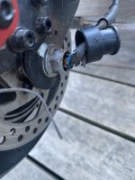
The cable is twisted at the axle in a way common to motors that have been allowed to spin their axle (insufficient torque arm/etc. I would back the axle nuts off to look at the dropouts, if they appear to have any scraping or damage (you may need to remove the motor/axle from them to see) then the axle has probably spun in them, and damaged those, too. The mechanical fix to prevent this is a good pair of perfectly-fitting-the-axle torque arms (or at least one on the solid-axle side) well-secured to the frame, and not just the not-usually-enough tabbed washer I can see in the image, which appears to be pointing the wrong way (up, rather than down into the dropout).

When the axle wires get twisted up, and the insulation damaged as you see, it's common to have shorts between the wires. If it's phase-to-phase shorts, that usually blows FETs in the controller, which can make it not operate at all, or run roughly, etc. If it's hall-to-hall shorts, it usually causes the controller to be unable to determine motor position, so it runs roughly, or may refuse to spin the motor from a stop in certain positions, etc. If it's hall-to-phase shorts, really bad juju can happen, as that's battery voltage stuff on phases feeding into low-voltage stuff on halls, and it can blow up all sorts of stuff (halls in the motor, various parts in the controller, even other things outside the controller like throttles, etc).

Sometimes you get lucky and no actual component damage happens, but the interference from the shorts causes bad behavior. In these cases you can repair the cable and it fixes the issue, once the axle is mechanically secured against it happening again. Fixing the cable usually means opening the motor and pulling the cable thru until the damaged part is inside the motor, then you cut the damaged area out of the wires one at a time (so you can't mix anything up) and then reconnect the wire to the matching internal motor wire.


If repairing the cable doesn't fix it, there is probably component damage. If the motor halls all work per the tests at ebikes.ca Learn-Troubleshooting, then you can do the FET tests there to see if the controller is still working.
Wow thanks for a realt useful answer.
I will start repairing the cables. Saw a YouTube of how to do, seems straight forward.

Crossing fingers that there is no other component damage :)
 
When the axle spins out, you can have random shorts between the wires that can damage the motor hall sensors or the controller output FETs or sensor inputs. Once you get the wires repaired, you can test the senors and controller.
 
When the axle spins out, you can have random shorts between the wires that can damage the motor hall sensors or the controller output FETs or sensor inputs. Once you get the wires repaired, you can test the senors and controller.
Thanks.

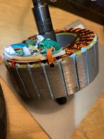
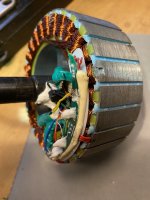
So now i have repaired the wires (disassembled the motor, and replaced and resoldered the wires, like this video
).

The motor is having the same issue as before.
Guess I will go on to test hall and controller, as per the link from amberwolf

P.S. Also I noticed, that if hold the wheel with my hands, before applying the throttle, it sounds like maybe the inner part of the wheel is spinning, but not the outer part. Is this intended?

P.P.S When the wheel is spinning, the speedometer only ocansionaly displays a speed other than 0km/h
 
Last edited:
P.S. Also I noticed, that if hold the wheel with my hands, before applying the throttle, it sounds like maybe the inner part of the wheel is spinning, but not the outer part. Is this intended?
With a geared hubmotor, that means the motor is spinning in reverse, so you need to either use whatever self-learn or reverse function the controller has, or if it doens't have those, manually try the different phase/hall wiring combinations until you get the lowest battery current draw with the wheel spinning in the right direction off ground with as little noise as possible.

P.P.S When the wheel is spinning, the speedometer only ocansionaly displays a speed other than 0km/h
If it doesn't have a separate wheel speed sensor, it means it is having trouble reading the motor hall signal(s).

If it has a separate wheel speed sensor, it means it is having trouble reading that, assuming you are manually turning the wheel (or riding it). Usually this is a white wire in the motor cable, but color coding isn't truly standardized.

Ok, so hall test seems to fail on one of the three sensors

If you're not testing with it connected to the controller and the controller turned on, the hall signals aren't really valid, as the power for the signals comes from pullups inside the controller on each signal line. (or you provide this externally with a manual pullup resistor to 5v on the signal line you are testing, as well as the 5v and ground to the sensors).
 
With a geared hubmotor, that means the motor is spinning in reverse, so you need to either use whatever self-learn or reverse function the controller has, or if it doens't have those, manually try the different phase/hall wiring combinations until you get the lowest battery current draw with the wheel spinning in the right direction off ground with as little noise as possible.


If it doesn't have a separate wheel speed sensor, it means it is having trouble reading the motor hall signal(s).

If it has a separate wheel speed sensor, it means it is having trouble reading that, assuming you are manually turning the wheel (or riding it). Usually this is a white wire in the motor cable, but color coding isn't truly standardized.


If you're not testing with it connected to the controller and the controller turned on, the hall signals aren't really valid, as the power for the signals comes from pullups inside the controller on each signal line. (or you provide this externally with a manual pullup resistor to 5v on the signal line you are testing, as well as the 5v and ground to the sensors).
Hi Amberwolf,

Firstly: about the first part of your answer, regarding motor spinning in reverse: SO this is not an issue right, i dont have to do anything about what i experience here?

Regarding hall: I have tested with controller connected and turned on. I got fine 0 and 5V readings on two of the halls when manually spinning the wheel slowly in reverse. (measuring from gnd to hall pins on/in the connector).

THe hall is a honeywell ss41-f. I can find a local vendor who ships the ss41, which would work fine as a drop in, but the sensor costs 1 eur and the shipping costs 14 :D.
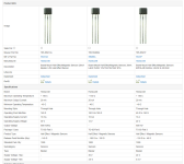
So was hoping one of these in here could work, since the store is right next to my work place:

For instance SS466A og the SS413A
THink either of these will work?

Mu guesss from below comparison is that it will work fine
1689144730632.png
 
Last edited:
Hi Amberwolf,

Firstly: about the first part of your answer, regarding motor spinning in reverse: SO this is not an issue right, i dont have to do anything about what i experience here?
It's an issue in that it wont drive the wheel while running in reverse. If this persists, then to fix it you'd need to either run the self-learn function of the controller, or use it's reverse function, or if it has neither of those you'd have to manually try the different phase/hall wiring combinations while testing current as I previously noted.


Regarding hall: I have tested with controller connected and turned on. I got fine 0 and 5V readings on two of the halls when manually spinning the wheel slowly in reverse. (measuring from gnd to hall pins on/in the connector).

If the third hall doesn't do the same thing the other two do, it's usually a wiring fault rather than a hall failure--any break in the wire from hall signal to controller prevents getting the pullup voltage to the hall or the hall signal to the controller to be able to test it.

If the hall itself doesn't work, it can be replaced with pretty much any SS41 / SS411 type of bipolar latching open collector output sensor that can run on up to 5v+ and tolerate 5v+ on the open-collector signal line.

Any hall that actually outputs a voltage isn't appropriate, it needs to ground it's output (open collector) when active, and open-circuit the output when inactive, so the controller pullup on the signal line does the job it needs to.

It *might* still work with a hall that outputs 5v when inactive and grounds when active, but the pullup inside the controller may interfere with this operation.

It has to be bipolar, so it detects both north and south magnets.

Needs to be latching so it holds it's output from one magnet pass until the next one comes by to switch it again.

Note that there are some hall sensors where the same part number (like 41) has several subsets of features, so that say, F might mean bipolar latching but G means unipolar nonlatching, etc. So before you order make sure you know what the full p/n is that you need from the datasheet. (it can be confusing).

The controller usually outputs less than 5v on hall power, so it may have to be able to operate reliably on less than 5v, but should be tolerant of voltages higher than that.

The pullup voltage in the controller on the signal line is usually 5v, so the signal pin has to be tolerant of at least this voltage or higher (noise spikes can be induced on the signal wires in the motor cable, so higher voltage tolerance on this pin is sometimes useful).

I would guess that the SS413A is a closer match than the 466, but the specs listed there are not complete on all of each listing so I'm not certain. It doesn't say it is latching, but the 466 does, but the 466 doesn't say it's bipolar while the 413 does. The 466 will run on a lower supply voltage so it could be more tolerant of brownouts on the 5v supply line from the controller, but there's no spec on the 413 listing for that.

So...I'm not sure which of those two is a better option.
 
It's an issue in that it wont drive the wheel while running in reverse. If this persists, then to fix it you'd need to either run the self-learn function of the controller, or use it's reverse function, or if it has neither of those you'd have to manually try the different phase/hall wiring combinations while testing current as I previously noted.

Ok, i am a bit confused. So my wheel is running in the right direction. But if i hold the wheel tight it with my hand, before start pushing the throttle, it sounds like something inside the wheel is spinning.
I found this old thread on using the self-learning. Last post seems leget, i will try that.

If the third hall doesn't do the same thing the other two do, it's usually a wiring fault rather than a hall failure--any break in the wire from hall signal to controller prevents getting the pullup voltage to the hall or the hall signal to the controller to be able to test it.
I changed all the wiring yesterday, so don't hope the wiring is an issue. Anyways i will swap the yellow (faulty) hall wire in the motor with one of the others (re-solder), to test if it is the sensor or the wire.

I will order a SS41F, to be sure i get a compatible sensor.

Thanks again!
 
So my wheel is running in the right direction. But if i hold the wheel tight it with my hand, before start pushing the throttle, it sounds like something inside the wheel is spinning.
Ah.

If the motor is actually turning the right direction in that situation, that usually indicates the clutch is broken, if it's a geared motor. If it is not a geared motor, then the magnets may no longer be glued to the rotor backiron, and so those may be scraping around the backiron being dragged by the fields of the stator.

If it's a geared motor and the controller is unable to tell which direction it's going until it actually starts moving (a problem I had with a Lishui controller on Fusin hubmotor about a decade ago), it might normally start forward, then detect a current spike from the load (you holding the wheel or it being on ground with you riding on the scooter) and instantly change direction so the load goes away. (my LIshui / Fusin did the opposite, if there was insufficient load at startup it would reverse (just once) and then spin that way until input command ceased and then retry when recommanded to go.)
Thanks,

Will check the magnets :D
(I dont think it has geares - the motor is similar to this one)
 
Sounds like all the magnets came unglued.
Time to take it apart.
Ye, Will take it appart again, when I am back from vacation :)

Re-glue the magnets and replace the faulty hall sensor (if it is indeed faulty)
 
Just wanted to update.
I replaced a faulty hall sensor, and now it all work like a charm :D.
THanks a lot for the help

IMG_9327.jpgIMG_9326.jpg
 
Sounds like all the magnets came unglued.
Time to take it apart.
I have the same problem with my kugoo m4 motor 500w the magnets are rubbing it has no power when I sit on it when I checked the magnet they weren’t unglued but it was hard to turn
 
I have the same problem with my kugoo m4 motor 500w the magnets are rubbing
If the magnets are actually rubbing, then something is physically misaligned between rotor and stator, or something has physically come loose inside allowing it to rub on the magnets (or vice-versa), or the motor casing is not correctly supported on the axle, etc.

You can follow the rub marks to see where the misalignment or loose part(s) is.
 
I have the same problem with my kugoo m4 motor 500w the magnets are rubbing it has no power when I sit on it when I checked the magnet they weren’t unglued but it was hard to turn
Sounds like it has destroyed axle bearings.
 
Back
Top