6.4 kW MBS eMountainboard build

RideTheIon

10 mW
Joined
May 5, 2015
Messages
24
Location
Finland
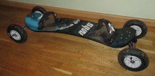
I'm excited to start building my first electric mountainboard.
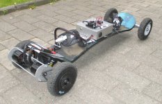
The ESC, motors and battery pack will be arriving in a few days. I took a few pictures of the other components.
Maybe seeing them laid out and later mounted on the board will help someone else out with their own build.
When the build is done, I'll post a complete list of components.
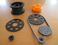
Mech_parts_eMTB-2015.jpg

View attachment 2

Board_eMTB-2015.jpg

My spirit guide for this build is MrRocketman. Big thanks to him for not just the cool things he does
with electronics+mountainboards, but for sharing the instruction, pictures, videos and 3D-files!

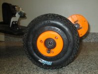
Today I got a print of the ‘Wheel Insert Inside‘. The part fit the MBS TriSpoke hub perfectly.
I'm using a bigger wheel-sprocket than MrRocketman and unfortunately the bolt pattern is also slightly larger.
Luckily tweaking a 3D model is a lot easier than tweaking a physical object.
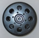
The holes on the sprocket are also smaller, so I'll have to drill them out to 6 mm.
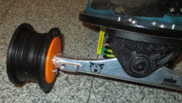
Wheel_insert_eMTB-2015.jpg

My gear ratio will be 54/12. The motors are 170 KV and the battery is 37 V @ 10 Ah.
I calculate that with 8 inch wheels, the theoretical max speed is 40 km/h.
I'm not sure how much voltage droop I'll be seeing with max load, so maybe 35 km/h is more realistic.

Still need a battery enclosure. I have my eyes on an aluminum case for a local supplier's website.
When I get the batteries, I'll make a last minute measurement that it fits.
Maybe plastic would be smarter with components rated to 200A, but style before safety :wink:
Still haven't decided should I ground the case or not. The circuit breaker will be mounted on the top of that case and I'll
be passing the positive lead though the case, so I'm put off by idea of sharp edges, voltage difference and high amps.

The motor mount I'll figure out when I have the motor in hand.
I have standard MSB matrix trucks. The truck have ~8 mm threads for mounting a brake and smaller holes on the bottom.
I'd rather make a custom part that bolts on rather than crimp on a ready-made motor mount.

I'll post updates of how the build is going.
If anyone has any suggestion or improvements, I'm all ears.
 
Looks nice.
Instead of the printed wheel hub, you can just use the three holes on the hub itself. Then put some spacers on to get the gear in the right spot to line up with your motor. Probably already knew that though.
Where did you get the hub anyway? Is that in the 3d printed parts thread?
 
I ordered the hubs from http://shop.mbseurope.com
As a principal, I hate MBS's Europe pricing where 1 USD = 1 GBP.
But with postage 15 euros from UK and 110 euros from USA, I can get over it. Slap VAT on the US prices and the difference isn't that bad.

Thank for the suggestion. I had considered that earlier.
The TriSpoke hubs have the bolt holes a lot deeper than the aluminum hubs. Its 14 mm from the outer face of the hub to the spoke face.
Adding 6 mm so that the chains doesn't rub the wheel, the stand-off would have to be 20 mm. That's a lot of twisting on a few bolts.

I revisited the idea after reading your suggestion.
Fate or destiny has made the final decision for me. The sprockets have 8 large weight reduction holes at the same places as the hub's holes.
If I had ordered the aluminum hubs, I'd have the same problem. Those hubs have 5 bolts which would probably also have aligned in the worst way with the weight reduction of the sprocket.

Sprocket-holes-verus-hub_eMTB-2015.jpg

Tweaking the wheel insert was not as easy as I had though. I tried it with FreeCAD and got nowhere.
Hopefully my friend that owns the printer is better at this than I am.

I found a site that can be used to convert the hole-to-hole measurement system that electricscooterparts.com uses to something more engineer friendly, distance to center of sprocket.
http://www.cleavebooks.co.uk/scol/calpolyg.htm

The sprockets MrRocketman used were triangle pattern with 33 mm sides.
Number of edges = 3, length of edge = 33 units gives a circumradius of 19.1 units.
The sprockets I have are hexagon pattern with 22 mm sides.
Number of edges = 6, length of edge = 22 units gives a circumradius of 22 units.

So at least now I know the exact amount that the holes have to be moved to match my sprocket.
 
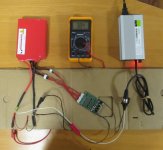
Today I charged my lipo for the first time.

Here's a pic of my test setup.
I arced the lipo the first day I received it. I was trying to solder a temporary connector onto the lipo leads with a 40W iron. After about an hour of turning the battery and globing solder on the leads, I pressed the half done connector against something metal.
It burned a few spots on my palm and scared the crap out of me. Now I'm a fan of keeping the lipo leads far away from each other.
I ordered 8mm bullet connectors and a 200W iron so I don't have to play with the live leads any longer than necessary when I'm doing the final wiring.

Lipo-charging-test-setup_eMTB-2015.jpg
I managed to overthink the BMS board and thought that discharged/load meant that I needed an external resistor for the balancing.
I sent Zecotec Ltd a message and they replied that there is no need to connect P- if you will use BMS for charge only.
So the charge balancer and cut-off / current limited output are semi-separate circuits and I'm free to use both or just one.
Since I'm only pulling the 5A charge current through the board, I connected the board with 16 AWG instead of the minimum 1.5 mm2 in the instructions.

View attachment 1
 
I installed my second iteration of the motor mount.
I'm happy enough with the fit to have it cut out of aluminum.

I was originally thinking of tighten the mount to the truck by welding a piece of aluminum onto the mount, then drilling a hole to bolt it to the truck.
After mounting the print, I noticed that I either need spacers for the wheels or then I need to think up something else.

View attachment 1
For the final part, I'll replace the cable tie with a metal clamp that are tightened on both sides of the bolt.
The mount prevents the bolt from turning, so it should stay in place.

Motor-mount-proto2-side.jpg
The metal part will be a cm longer.
Now, if I slide the motor the whole 1.5 cm that the mount allows, the shaft touches the wheel.
I could shorten the shaft of the motor, but that sounds like an easy way to destroy the motor.
 
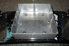
The battery enclosure drilled and test mounted onto the board.

Battery-enclosure-empty_eMTB-2015.jpg
The enclosure I ordered is really tight for the battery, BMS, charger port and wiring.
I'll have to mount the display and circuit-breaker on top of the enclosure instead of inside.
I'm also going to place the BEC and receiver on top of battery instead of placing them next to the ESC.

To make the BMS fit beside the battery, I dremeled the side supports on both sides. The pencil mark shows the placement of the battery.
I didn't account for the carriage or coach bolts sticking out that much. I'll cut a 3mm thick piece of plastic to raise the battery and angle grind the bolts if they still press against the battery.
I'll probably have to dremel more of the side supports to clear the raised battery.

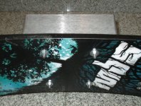
Battery-enclosure-mounted_eMTB-2015.jpg
I went overboard on angling the bolts. To compensate for the deck straitening out when/if I land a jump, I tried to angle the bolts so that the they are semi-vertical when the deck is at it's flattest.
Now they are really angled at rest and completely vertical at max flex.
Anyway I've jumped on the center of the board while trying to shake the enclose and it feels solid.
By some odd stroke of luck, I was able to get the enclose dead straight in respect to the board, so I'm happy with it.
Later I'm getting a piece of silicon sheet to place between the deck and the enclose. That’ll decrease the rattling of the enclosure, even though the bolts will still transmit a lot of the vibration.
 
I'm optimistic that I can take my first ride next week.
The motors at a shop being drilled and the last printed parts are coming to life this weekend.
The battery case is almost complete. I had to angle grind the coach bolts to make clearance for the battery and add a 3mm sheet of plastic to the bottom.

The motor mount seems sturdy.
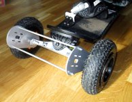
The sides are connected with M4 threaded rods. The rods are spaced using 6mm aluminum tubes.
I shrunk heat-shrink onto the middle parts of the rod to pad the tubes.
I was going to go with 3 rods, but the hobby shop I went to only had one package of the tubes.
I might add it later for appearance, but I doubt it will make the cage significantly sturdier.

Motor-mount-complete-back.jpg
I was originally thinking of attaching the cage to the trucks by having an L-piece welded to the side structures of the motor mount.
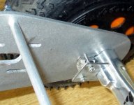
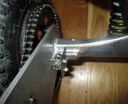
I went for an easier solution. I dremeled two pieces of 3mm steel to fit the contours of the truck, then attached them using countersunk M3 screws.

Motor-mount-to-truck-attachment.jpg
 
Thanks, its nice to hear that this thread is being followed.

On Thursday I took my first ride with only one motor attached.
Within 10 min I had a motor failure. The hex-screw that holds the shaft to the housing had come loose when the shaft was being drilled.
I didn't even know the shaft was removable, I had assumed that it was pressure fitted to the housing with tons of force making it permanent.
I tried to glob super glue on the end of the housing and rotate the shaft in hope that it would seep into the joint.
That held for about 1 minute, grinding enough clearance between the shaft and housing that I was able to twist the housing off without tools.
Taking the gear off the motor is a big task, so I fixed it with the motor still on the board. I coated the shaft and housing in super glue,
propped the board on its side so the shaft is sitting on a piece of metal. Then I took a hammer and pounded the housing back on to the shaft.
When I got it to the bottom, the screw was about 15 degrees off from the slot on the shaft. I tried to twist it to the correct position, but no dice.
I hope that they are now joined for life. I attached the second motor before taking the next ride, so that there is less strain on the fixed motor.

What really surprises me is that after a few km cruise, the motor seems OK.
Right after the glue and hammer, the fixed motor got much hotter than the pristine motor after a few minute ride.
Today after the ride, they were somewhat even temp, the fixed motor being a little bit hotter.
When I turn the wheels by hand, there is a difference, but not as much as I expected when I was hammering the hell out of the motor.
It's probably a smart idea to order a new motor soon, but at least now I don't have to decide between €€€ for fedexing a new motor
or waiting a month to ride it the next time.
The cage is not as sturdy as I had originally though, so it really needs both motors to balance things out.

Board-2015-07.jpg
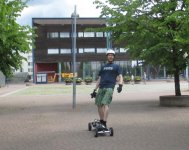
Tori-ride-2015-07.jpg
I'm kind of disappointed in the rattling when I first start to accelerate from standstill.
To accelerate without rattling, I have to slowly pull the trigger till the motor engages, them a slight pull on the trigger and I'm off.
The acceleration at first is walking pace. This sucks, because the reason I selected the 2 * 3.2 kW motors is so it would take off like a rocket.
Sometimes it takes a few tries to get it moving :(
I'm still not sure is the rattling mechanical, does it have to do with the synchronization of the motor/ESC or the control being too sensitive.
A first it rattles heavily, then if I continue to press the trigger, the board stops moving forward and the motors screech.
So it sounds to me like it's a synchronization problem.
The rattling is not just the cage. The truck, back wheels and cage all seem to shake.

If anyone has any suggestions on tuning APS's dual-ESC for a better launch, I'm all ears.
 
Good looking board, just be careful with the length of your battery wires running to the ESC. Voltage ripple increases as your battery wire length increases, too much can kill your ESC Caps and then the ESC itself. You can either ignore it, add more capacitors to your ESC or move your ESC to your battery box and run longer motor wires, which are OK to run a little long for this application.
 
torqueboards said:
They weren't made to start from a stop. You'll need to kick off especially with the bigger wheels it's much harder to stand from a stop.

If you want to start from a stop. You'll need to add in sensored motors.

If you want to start from a stop buy a good controller......
 
If you want to start from a stop. You'll need to add in sensored motors.
I read up on how the sensorless ESC works and now I understand why the board burns rubber when I'm not standing on it
but studders when I'm trying to ride it. I was hoping there was a magic parameter that would fix this.
Adding hall sensors seems doable with a kit from Equals Zero Designs, but this would mean replacing the ESC.
Maybe I'll take that as a winter project, but till then I have to make do with a shaky start.

just be careful with the length of your battery wires running to the ESC.
Thanks for the head up.
If I'm replacing the ESC later, that would be a good time to integrate a capacitor bank or one big capacitor.
What kind of capacitance is needed for a 65 cm run of cable from the battery to the ESC?
It seems that 680µF @ 63 V is the largest low ESR capacitor that I can find locally.


I was hit with more motor trouble :(
The pristine motor (not the hammer augmented motor) seized up while I was riding back from work today.
Here's a picture of what happened.

Am I doing something wrong with the motor?
It looks like the part holding the magnets rubbed against the face of the motor and produced enough friction to melt some metal.
It was a cold day, so the motor wasn't especially hot.

When I took apart the other motor, the cylinder holding the magnets and the housing were not attached to each other.
They have some grooves or tracks that prevents the inner cylinder from spinning in relation to the housing,
but nothing is preventing the inner cylinder from moving back and forth.
Is this normal?
Would it be a good idea to open up the motor and super glue the inner cylinder to the housing?
Or would I be breaking some important function that this setup has?
 
I should have sensored motors 50mm soon and I have sensored 12s escs. You can also use the e0 designs external hall sensors + VESC and/or my ESCs.

There is a set screw on the back side of the motor that holds the motor shaft and allows the motor shaft and motor to spin together.

I am assuming because you were trying to start it from a stop and with a bigger drive wheel it can cause much more force and you might have separated the set screw on the motor shaft and motor which perhaps damaged the motor?

You can glue it back but these motors are also pretty precise. IMO it's usually not worth the hassle of messing with it and it's more cost effective to buy a new one. But I'm sure, you could put it back together again.
 
Thanks for the advice.
I'm looking around for an assembled VESC.
I also opened another thread to get some help in selecting better motors.

I used chemical metal (epoxy with metal powder) to glue the flux rings to the housing.
The motors are definitely screwed up, but at least now they are balanced in that they are equally screwed up.

The gearing does seem to be off.
Now that the motors are not at their best, I need significantly more speed for the motors to not shutter.
This same effect seems to come, when the motors heat up and loose efficiency.
I need less speed to start cruising smoothly when I begin my run than at the end.

I don't know how fast the board is going at 75% throttle, lets say 30 kph.
This seem to be the top speed in that after that the motors really start the scream.
I'm not comfortable exceeding this speed, partially because of self preservation, but mostly because I'm afraid I'll break the motors.
Do these setups normally run at 100% throttle or is it wise to cut a little bit from the top?

If I change the motor sprocket to 11T from 12T, will the motors leave its comfort zone earlier or will the effective top speed be the same?

I tried to tune the ESC, but there wasn't any mention that the USB-dongle wasn't windows 8.1 compatible :x
I had fired up the program at work using a vmware guest win7. Worked without a glitch.
At home my only windows computer is win 8.1. Tried to get the connection up.
When it didn't work, I tried to power up the receiver then the whole board. This fried the ESC's programming port.
I installed win XP on my laptop using vmware and that identified the dongle, but the programming port doesn't respond.
The dongle still gives out 5v, so replacing the dongle won't help.

I can still change the timing advance using the transmitter.
Haven't had a chance to test out the difference yet.
 
I always think if you don't plan to use the added top speed. Use a higher reduction to get more torque that way the motor isn't over-stressed climbing any hills. More torque also equals a lot less cogging on start-up and on a dual motor you can pretty much start from a stop on flat ground. However, with uneven pavement it's a bit harder and the initial kick is required for an unsensored setup.
 
You can glue it back but these motors are also pretty precise. IMO it's usually not worth the hassle of messing with it and it's more cost effective to buy a new one. But I'm sure, you could put it back together again.
That is definitely the good advice that I just didn't take. I probably put 3 hours into taping, gluing, filing ect. I was able to ride to work. Then while showing demoing the board to a colleague in the parking lot, the clips holding the magnets in one of the motors totally disintegrated.
The magnets slid every which way in the motor and it seized hard. I removed that motor and rode home slowly with one motor.
The next day I fried the other motor on a short few minute ride. In the end, I rode for under 30 min versus the 3 hours of fixing.
So yes it is possible to endlessly frankenstein the motors back to life, but its not really worth it.


I ordered new motors from China and sent 4 of them to the shop to have their shafts drilled for the sprocket's roll pins.
I'll post a review and teardown of them when I've put them through their paces. My initial impression of them is very positive.
I had overheating problems with APS's motors from day one. That problem of course got worse when I pounded the bearings and glues them up.
These motors were only mildly warm after I floored it home from work today doing 2.8 km in under 7 minutes.

Before having the shafts drilled, I fixed up the motor mount. The motor mount had loosed up a lot and the alignment had probably changed with it.
Roll pins seem totally idiot-proof, but the placement is set for life.

Motor-mount-Chemical-metal-fix-2015.jpg
I'm starting to regret not having the side plates welded to the trucks. I had used metric bolts, since I didn't have whatever MSB uses on hand. They had loosened up a lot and were not preventing the side plates from rotating. This in turn enlarged the profiles on the plates.
I used chemical metal to first fix the bolt in place. Then I ground grooves in the surface of the chromoly trucks with a dremel cutting wheel. Applied more chemical metal and fixed the plates to the trucks.
The chemical metal doesn't seem to stick very well to the EN6082 aluminum that I used for the side plates, so I'm hoping it's enough that it bonds well to the trucks. After 4 rides and flipping the board today, they still seem solid, so I'm optimistic this will hold.

I also replaced the aluminum tubes connecting the plates. The previous tube walls were 0.5 mm thick and even the smallest tap would warp them. I had a 4mm threaded rod going though tubes, but those would bend as well.
The new tubes are by spec 6mm od with 1 mm wall, but the 4mm threaded rod didn't want to slide though the tube. I attached a few nuts to the end of a spare rod and drove that through the tube with a power drill. Kind of screwed up the rod, but left nice treads in the tube.
I then drove new rods through the tubes and attached the ends with locking nuts.
The new rods feel more rigid. Since the rod is kind of attached to the tube over the whole distance, I probably won't see as much shortening of the tube when its tightened.

The problems going past 30 km/h was caused by the motor mount rattling and the old motors dying. Now I can go as fast as my courage gives way and it pushes forward like a train.
I'm getting a moderate amount of wheel wobble at fast speeds, but I don't want to tighten the trucks since doing a u-turn already takes a few lanes.
Maybe when I learn to lean more into the board, I can pull off a tighter turn and then tweak the truck settings.
 
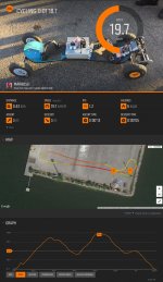
Here's a short video and speed results of a run.

View attachment 1
It's really cool to now know how fast I'm going instead of a guestimate.
Bit thanks to Markus for lending his Suunto Ambit3 Peak watch.

The GPS watch gave a top speed of 39.2 km/h and I'd say the throttle was at 90%.
I'm not surprised, I'm shocked that the board can outdo the theoretical max_rpm*gear*wheel_size calculation.
I work in IT where 3/4 of the advertised max throughput is already a miracle.
I have to get some protective gear and redo the run at full throttle with only misguided self-confidence in my system.

EMTB-Speed_test-Suunto_movescount-2015.jpg
The original content is on instagram with the hashtag #electricmountainboard
http://websta.me/tag/electricmountainboard
https://www.movescount.com/moves/move73428405
 
Back
Top