A PWM Controller For Each Cell?

Status
Not open for further replies.

safe

1 GW
Joined
Dec 22, 2006
Messages
5,681
A PWM Controller For Each Cell?

:idea: Here's an idea...

I've proposed something in the past I called "Distributed Pulse Width Modulation" before as a technique to implement a Low Voltage Cutoff and other functions for each cell. In that idea the PWM was done by a single master that was then connected to the MOSFET's distributed to the cells in a daisy chain configuration.

Where I'm taking a step forward with this is now I'm thinking:

"Well heck... do we really need a 'master' controller to supervise the others?"

...and I came to the conclusion that maybe you do not.

What if you had a small controller with nothing but a PWM logic part, a capacitor to hold the temporary charge of the previous battery in the daisy chain and a MOSFET to act as the gate. These small controllers might be made for a very low price, so maybe they only cost $5 each. Since in a daisy chain the voltage difference between one point and the next is small the MOSFET's need not be so high powered to handle it and can be made cheaply. (this was already figured out before, big voltage differences at the gate mean higher heat, so lower the difference and you lower the heat) It's not necessary for the PWM to be synchronized because the capacitor will hold whatever charge is delivered from the previous cell in the daisy chain.

This is how it might work...

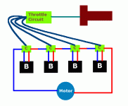
The throttle is set up so that all the controllers see more or less the same throttle voltage. Each controller has a voltage cutoff that is appropriate for the type of battery chemistry that you are using. (so SLA would be 10 volts, Nickel 1.0 volts, LiFePO4 2.5 volts) Amazingly you could even MIX chemistries with this idea. The throttle would then allow that cell to deliver it's current as long as it was able to do it and then once it cut out everything would be shut down because the daisy chain would be broken. You could still do balancing if you wanted, but it would not be required.

If you really wanted to get sophisticated you could use a centralized monitoring system to watch the cell voltages and you could control the THROTTLE signal to the controllers. This would do the best possible job of balancing because the "runts" could be given less throttle than the stronger cells. Cell voltage measuring would be easy to do within the controllers because when the MOSFET's are closed there is no "common mode voltage" to worry about. (so you measure in the gaps between PWM pulses)

:arrow: The THROTTLE.

...this way you compartmentalize the problem. Each cell gets it's own controller and you only deal with the throttle as the way to control it. All the low voltage cutoff and even the high voltage cutoff functions are delegated to the controller.

Charging might also use the SAME controllers in a way where each controller has a separate wire that allows a DC voltage to be given to it. The control logic for charging could also be built into the controller.

Either this is "brilliant" or I've missed something... :lol:

:arrow: Okay... find a hole in my idea...


This actually might leapfrog past the idea of a daisy chained PIC system which relys on communication between cells using software. This reduces the problem because the MOSFET's effectively "divide and conquer" the "common mode voltage" problem that is at the root of all the difficulties.

This would deliver most everything that a "Smart Battery" could give without much (or any) of the software to worry about. :)
 
the little bit of exrta energy you would get from having all the cells get to the LVC voltage at once would most like be lost due to all the energy lost in all those mosfets.
 
dirty_d said:
the little bit of exrta energy you would get from having all the cells get to the LVC voltage at once would most like be lost due to all the energy lost in all those mosfets.
Nope, the smaller MOSFET's can have much lower resistance than their bigger relatives. (you just shop around for the right type... it all ends up about equal)

Next...
 
safe said:
dirty_d said:
the little bit of exrta energy you would get from having all the cells get to the LVC voltage at once would most like be lost due to all the energy lost in all those mosfets.
Nope, the smaller MOSFET's can have much lower resistance than their bigger relatives. (you just shop around for the right type... it all ends up about equal)

Next...

Uh, actually, he's right. If the cells are properly matched, the difference in capacity will be minuscule. What did Doc manage to get his down to? Something like 0.25% difference between cell groups? Even with a monster pack that's mere seconds of difference in runtime. I'm pretty sure that the losses from this thing are gonna make up that difference, though you still probably wouldn't notice it. You'll get more of a difference in runtime if you happen to be hit with a 5mph gust of wind on your ride.
 
Link said:
What did Doc manage to get his down to? Something like 0.25% difference between cell groups? Even with a monster pack that's mere seconds of difference in runtime.
Well let's get our facts straight here. Doc did publish some runtime numbers for a set of cells that were brand spanking new and in that pristine condition they are likely to still be in a state of relative equality.

However, over time cells age differently and you do get the "runt" cell problem that crops up as one cell out of a group gets progressively weaker and weaker until the entire pack is dragged down by the behavior of the one "runt". On my present bike I've got one cell that is becoming the "runt" and today it ended a ride at 11.3 volts when the others ended the ride at 12.2 volts and 12.5 volts. If I kept going the weakest cell would simply absorb more and more damage, so I have to cut the ride short. With a system that adjusted the throttle on each cell I could run the weak cell at less throttle than the stronger ones and get a full ride out of the rest. Right now the strong are not doing very much. "Runt's" always try to keep up... and that's the problem, they exhaust themselves prematurely and that's why you have to stop when the strong cells are still full.

In the classic balancing scenario you do the usual things like shuttle energy from the strongest cells to the weaker cells using some sort of switched capacitor solution or something like that. In the least efficient balancing systems they simply throw energy down the drain for the sake of equalizing everything. But even the best balancing system is not going to be as effecient as having a throttle on each cell, it just can't... because these individualized controllers use MOSFET's that have low resistance to them.

What this idea does... and let me be clear... is that it brings most of the features of the "smart battery" into play without having to be so "smart" with some software solution. It's very possible to get the very desireable behavior of the "smart battery" without needing the whole framework that requires computer logic and programming.

:arrow: Do people see this yet?

I get the feeling that people aren't really understanding the idea yet and so I need to repeat the idea about a dozen times before it starts to register. (eventually people will start to get it)

What this does is allow LVC, Balancing and Charging using a correct algorithm all on a cell level. It's (I believe) a very clean approach to solving it and not one that has been discussed here yet.

:arrow: I dare anyone to show a similiar invention anywhere.
 
safe said:
:arrow: The THROTTLE.
Let me get back to it...

What I'm thinking is that the voltage measurement that is possible between pulses when the MOSFET's are closed is something that could be "pooled" since the "common mode voltage" problem becomes not an issue. Your throttle could run through some circuit that used a simple comparator to "pulldown" the throttle voltage based on what the voltage measurement was for that cell. So if the voltage measurement is suggesting that a cell is the "runt" then you know by comparision to the cell voltage measured of the other cells that this "runt" cell needs it's throttle lowered.

We need to remember that the CENTRAL PROBLEM of all voltage measuring systems comes back to that nasty "common mode voltage" issue. By placing the MOSFET's in between the daisy chain of cells you are able to for a microsecond between pulses have a broken chain. It's when the daisy chain (series connected cells) is cut off from the group that voltage measurement is possible.

Once people see this they should go "aaaaaahhhhhhhh".... :D
 
safe said:
Do people see this yet?
Nope... the "Foes" feature seems to be working pretty well. :lol:
 
safe, what if instead of using PWM you just have the circuit for each cell wait till it gets to the LVC voltage then disconnects it from the pack and connects the two cells around it together? you don't have losses from PWM and no communication is needed. you get the same end result with less complexity.
 
I'm still unsure what exact topology you are proposing. If you could supply a rough schematic or block diagram it would be most helpful.
 
safe said:
...a capacitor to hold the temporary charge of the previous battery in the daisy chain...

Does that mean, if you are drawing 30A from your pack, these caps have to support this current as well? You'll need beefy caps that'll hog valuable space. Sorry, your idea still eludes me.

Sputnik :idea:
 
Sputnik said:
Does that mean, if you are drawing 30A from your pack, these caps have to support this current as well? You'll need beefy caps that'll hog valuable space.
I suggested that as a way to get around the PWM synchronization problem that a distributed architecture would introduce. If all the MOSFET's had to open and close at the same time then there would be all kinds of issues about the signal being off and things getting jumbled. If you allow each cell and it's corresponding (and out of synch) PWM activity to be buffered with a capacitor then you can allow each cell to work alone.

But while I've already done the math on the MOSFET's from a previous discussion about such things (so I know it's correct) I have not yet done the math on the capacitors.

:arrow: However, think about it for a second...

You only need to store as much energy as can be built up between a cycle of pulses delivered from the PWM controller of the previous cell in the daisy chain. So whatever current you are dealing with will be divided by the period of the pulse, which is normally very short.

Normal controllers have a very large voltage difference between one side of the MOSFET's and the next, so when you are dealing with a pulse you are dealing with essentially 0 volts on one side and a high DC voltage (36, 48, 72+ volts) on the other. So the MOSFET's need to be able to handle the full brunt of the current and the voltage combined.

With these cell based controllers they only see the voltage difference between one and the next cell. So if you are using LiFePO4 you would see a voltage difference of 3.2 volts across the MOSFET's and the capacitor would need to be able to store:

3.2 volts * Current * PulsePeriod = TotalCapacitanceNeeded

...so a calculation is in order, but I'm just waking up and not currently in the mood to do it yet. (anyone can take a crack at it if they want)
 
dirty_d said:
safe, what if instead of using PWM you just have the circuit for each cell wait till it gets to the LVC voltage then disconnects it from the pack and connects the two cells around it together?
That was actually my previous idea. :)

You end up with a bunch of MOSFET's that could easily be doing something useful like actually doing the PWM but instead they just sit there doing very little. You also need a diversionary MOSFET to reroute the daisy chain so that a cell that is disconnected gets avoided.

This newer idea starts to make more sense because everything is more necessary and useful. It's elegant in that the throttle signal alone becomes the way to control each cell. Each cell esssentially has it's own throttle.
 
Randomly said:
I'm still unsure what exact topology you are proposing. If you could supply a rough schematic or block diagram it would be most helpful.
I didn't add the wires from the controllers to the throttle circuit that would hold the voltage measured for each cell. It's from these voltage wires that the circuit would do a comparision of the voltages so that the throttle can be pulled down sufficiently to act as a balancing mechanism.

Analogy

Sometimes an analogy is a good way to express the difference in how this might work compared to a standard controller:

"If a regular controller can be thought of as like a waterfall where the full energy of the stream is sent over the edge of the gate at once, this alternative vision might look more like the locks they use at canals where they gradually raise and lower the waters in stages. Each stage in the daisy chain only needs to lift or lower a small amount of the total energy."
 

Attachments

  • Cell Based Controller Diagram.gif
    Cell Based Controller Diagram.gif
    7.2 KB · Views: 2,176
The Backflow Problem

One of the most obvious problems that immediately comes to mind is backflow of the energy being stored in the capacitors through the MOSFET's in the backwards direction. MOSFET's don't have perfect behavior and they tend to "leak" in reverse. This might not be too significant a problem or it might be a major problem, but I just want to throw it out there as something that needs to be looked at...
 
Safe,

It seems to me that you will be loosing too much power in your cell disconnect mosfets (I assume at least one would be needed per cell for this purpose), and about the same loses for you bypass mosfet when it is on too. After all, their Rds ON is relatively high compared to each cell's internal resistance. Using low V mosfets will get you lower Rds, and you could use these low-V ones for the bypass/parallel ones no problem I think (since each cell will never ever go over 4V anyways). But for your cutout/series FETs, they have to rated for the full pack voltage, which will leave you with a reletively high Rds ON part, and thus introducing high loses during most of the discharge cycle. I mean a 4mOhm or so FET for each cell will raise your pack resistance by a huge amount considering that 10A LiFePO4 cell's internal resistance ranges from 2 to 10 mOhms...

But maybe I'm not understanding what you are getting at, since your last post (drawing) is not very clear to my eyes.

Pat
 
Capacitor Before or After?

If the capacitor is placed before the MOSFET in each cells controller then it's going to store energy based on the previous cell in the daisy chain. This is going to get all screwed up when you get to the end because the last cell would have nothing to plug up it's voltage and there would be no way to measure it's voltage either.

It doesn't take long to realize that the only realistic location of the capacitor is AFTER the MOSFET within each controller so that the capacitor is in essence locking up the energy of it's OWN cell. This makes sense... it also means that the voltage measurement is achieved by simply checking whatever is the maximum charge that the capacitor attains between pulses.

So the answer needs to be AFTER...

(hmmmm... what about the last cell?)

Update: This is wrong... skip down below...


file.php
 
ZapPat said:
Using low V mosfets will get you lower Rds, and you could use these low-V ones for the bypass/parallel ones no problem I think...
You must have followed my thread about the bypass configuration for cell management.

No, I'm not doing any bypass this time... it's a new concept... the idea is that there is no bypass, but the amount of energy permitted to be added at each step up the ladder is limited by the cells ability to lift. (it's strength being measured by the cell voltage) This is done by limiting the amount of time that the pulses are allowed open and so it will limit the amount of charge that the capacitor can build.

One of the things I learned is that the big MOSFET's tend to have higher resistance values than the smaller low voltage one's. For any given throughput of power the MOSFET's can either be few, big and high resistance OR many, small and low resistance and you end up at the same place.

The MOSFET resistance is neither better or worse than a standard controller. (it's about the same)

MOSFET's come in many shapes and sizes and I'm pretty sure that the right selection will make the idea workable.
 
yes, a rough schematic would be helpful. I have a feeling Kirchoff's law is going to bite you in the ass on this one without magnetics on each cell to do current transformation.
 
ZapPat said:
Please post a rough schematic of your idea using a simple 3 or four cell battery as an example (like your drawing, but with real parts and connections)
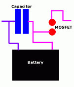
I'm thinking that the capacitor needs to be BEFORE rather than after... something like this... bascially the whole thing will work in a similiar fashion as a "switched capacitor".

Take the "switched capacitor" concept people have used to balance between cells and place it at the center of the system and it will start to make sense.

Each stage only lifts the voltage a small increment and that should mean that all the components only need to be strong enough to handle the increment and not the full load.

"Divide and Conquer" as they say... :)
 

Attachments

  • Cell Based Controller Diagram 002.gif
    Cell Based Controller Diagram 002.gif
    3.8 KB · Views: 1,832
safe said:
One of the things I learned is that the big MOSFET's tend to have higher resistance values than the smaller low voltage one's. For any given throughput of power the MOSFET's can either be few, big and high resistance OR many, small and low resistance and you end up at the same place.

The MOSFET resistance is neither better or worse than a standard controller. (it's about the same)

But you have one mosfet for each cell, so it seems to me that unless you can use very low V ones with correspondingly low Rds ON, you will end up with a higher overall resistance to your pack.

I'm just now checking your last post out, and I'm not sure you can get off using low V mosfets... I'll think about it. If you can it might be a plausible idea.

Pat
 
Randomly said:
I have a feeling Kirchoff's law is going to bite you in the ass on this one without magnetics on each cell to do current transformation.
You might be right in that the flow could be susceptable to all kinds of weird resonances that would reduce the output. But I would guess that if the dampening effect that capacitors can provide were done skillfully that you could smooth things out enough between PWM pulses to make each controllers MOSFET see a fairly reliable source of energy to draw from.

It's like locks in a canal system... if sufficient time isn't allowed to fill up the locks then the whole thing wouldn't work. There needs to be enough capacitance available so that no matter how out of alignment the PWM pulses might get things still flow smoothly.

Some serious debugging and tweeking would be required I'm sure! :)
 
ZapPat said:
I'm just now checking your last post out, and I'm not sure you can get off using low V mosfets... I'll think about it. If you can it might be a plausible idea.
MOSFET's tend to be rated in peak amps, peak voltage difference and most importantly maximum power transferred. The power transferred is small between stages, so you can pick MOSFET's that work better at that low power regime.

I did all this research on another idea and it did turn out possible... the resulting resistance of many small MOSFET's end up about the same as a few big one's.

And the small MOSFET's tend to be cheap too... so the price ends up pretty reasonable.
 
SLA might benefit?

This idea automatically places a capacitor buffer between each cell and it's MOSFET. This MIGHT improve the Peukert's effect for using SLA because the cell is not asked to give it's energy in sudden pulses, but instead is in a constant state of charging up it's own capacitor. The effect might be so small that it doesn't achieve much though. (actually most controllers have capacitors already, so this might not change much)

file.php
 
PWM Timing is Random

Since each cell is going to have different voltages (the only way that this system can judge the capacity left in a cell) this will mean that each cell will have an effectively different throttle setting relative to the other cells.

:?: What does the throttle do?

A throttle sets the "duty cycle" which is the length of time that the MOSFET is opened relative to the time that it is closed.

You could also set the "duty cycle" in any number of alternative ways so that it might be based on the period of the pulse or the shape of the pulse could be configurable. This is the sort of thing where you have to experiment to see what works and what doesn't. Some computer simulations would accellerate this education process as you could run all kinds of tests using differing ideas to see what works best.

You need to deal with the idea of the "perfect wave" where all the MOSFET's might be open at one moment as well as situations where all the MOSFET's are out of alignment.

With enough buffering by the capacitors you should be able to factor out all the nasty harmonic effects that could occur, but I'm sure that there will be some strange things that would happen in early testing.
 
Status
Not open for further replies.
Back
Top