Abnormally high rpm on overvolted escooter.

BLACK and RED: always 4.3V constant, weather the wheel is spinning or not

(BLACK and BLUE) and (BLACK and YELLOW) and (BLACK and GREEN) : fluctuates between 0.038V and
5.020V when spinning the wheel very slowly

When the wheel gets spinning a bit the fluctuating voltage of BLACK with BLUE, GREEN AND YELLOW becomes a constant 2.525V. That's what I'm reading on my multimeter.
 
Quick update. The first measurement turned out ok. When one voltage was at 5v, the 2 others were at 0.038v.

The problem is when I tried holding the wheel with my hand to simulate a little load. There was the usual screech slide mechanical noise, yes. But after that i measured the 3 combinations of BLACK with BLUE , GREEN and YELLOW and found that 2 combinations were at 5v while one was at 0.038V. So basically when one was at 0.038V the other 2 were at 5v for all 3 combinations. That was after a little load, which was me holding the wheel with my hand.

So basically with no load, the hall sequence is correct. With little load the hall sequence becomes wrong.

Btw, I don't know if this is important or not, but the first time that i held the wheel to simulate load, the sound was quite harsh, especially that mechanical slide screech sound. The second and third time i held the wheel, the sound wasn't as harsh.
Could it be that that sliding is messing up the hall sensor?
 
Now that I think about I actually had the same symptoms happening on a scooter that I fixed for my niece a while back.
The motor would stall occasionally and make that terrible noise. It sounds like a mechanical noise but it's not. I tried replacing the sensors but nothing changed, she still rides it.
I also noticed that the motor spun really fast with no load, under load it only went like 15 kph and had very little power despite replacing it with a 15A controller.

Looking back at it I'm certain now that the previous owner overheated the motor. I replaced the bearings and checked the stator on the shaft.
 
The hall signals go through a pattern where there is always one or two high. As long as they all toggle, the sensor are good. There should never be a spot where all 3 are high or low.

I would open up that motor and check the magnets to see if they are still glued on. You can usually remove one side cover to see the insides.
 
Have you tried all the hall phase combos? I have heard the incorrect combo sound like an audible squeak. Normally its a horrible chatter or buzz but you may want to exhaust all possibilities before opening it.
 
On the new controller’s product description page, I noticed this little blurb regarding the “learning” wire…

“ 6)With self learn wires (Self learn function only can be used when the PAS set at 2 or more)”

Was this requirement met during usage?


For anything you might have missed testing your BLDC motor, as well as hall sensor activation sequencing charts and other helpful tips. See this thread…
https://electricbike.com/forum/for...-motor-s-phase-wiring-hall-sensors-and-wiring


Regards,
T.C.
 
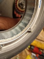
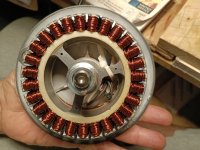
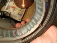
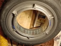
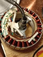
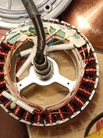
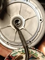
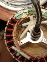
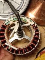
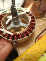
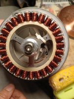
Here are some photos i took. How does it look? Since this is my first time i can't tell if something is wrong or not.
 

Attachments

  • IMG_20221228_220533.jpg
    IMG_20221228_220533.jpg
    1 MB · Views: 115
  • IMG_20221228_220432.jpg
    IMG_20221228_220432.jpg
    1.3 MB · Views: 115
  • IMG_20221228_220412.jpg
    IMG_20221228_220412.jpg
    1.2 MB · Views: 115
  • IMG_20221228_220401.jpg
    IMG_20221228_220401.jpg
    1.1 MB · Views: 115
  • IMG_20221228_220345.jpg
    IMG_20221228_220345.jpg
    1.1 MB · Views: 115
  • IMG_20221228_220336.jpg
    IMG_20221228_220336.jpg
    1.1 MB · Views: 115
  • IMG_20221228_220316.jpg
    IMG_20221228_220316.jpg
    1.3 MB · Views: 115
  • IMG_20221228_220332.jpg
    IMG_20221228_220332.jpg
    1,023.6 KB · Views: 115
  • IMG_20221228_220310.jpg
    IMG_20221228_220310.jpg
    1.1 MB · Views: 114
  • IMG_20221228_220255.jpg
    IMG_20221228_220255.jpg
    1.1 MB · Views: 114
  • IMG_20221228_220216.jpg
    IMG_20221228_220216.jpg
    1.2 MB · Views: 115
It looks pretty good inside.
It's hard to tell if the magnets are unglued from the picture, but there's usually a lot of debris when that happens and I don't see any. The windings don't look cooked, which usually happens if the motor overheats enough to damage the magnets.

The magnets are very brittle and easy to chip/crack. Be careful when reassembling to avoid a hard collision between the rotor and stator.

I don't like the way some of the winding wires are just loose and touching each other. These spots could wear through and short over time. They should be glued or tied so they can't rub.
 
I think I can. The motor doesn't go forward anyways. Will knowing the current under load help?
 
One thing I noticed on the controller picture is it says "sliding start". This may be a safety feature that prevents the motor from running unless it's already moving. On the scooter, you have to kick to get it moving, then hit the throttle. You could possibly spin it by hand if the wheel is up.
 
You guys wanna see a mis-wired QS273 that is taking silly current and making silly RPM? For an example of a bad setup? Took a vid trying to figure it out and asked the forums a while ago.

Here is a badly wired 273 motor. Ridiculous unloaded RPM was the hint something was wrong. Motor was rewired and achieved 55mph loaded on a 17" rim with street tires. In the end.

Yeah? Listen to how weird this one sounds.

[youtube]U-bSoJoje4o[/youtube]

Another vid. You might not be able to see this one... 154mph unloaded.

https://www.facebook.com/100000610140120/videos/4375012112529084/
 
Back
Top