Active pre-charge/inrush control

Not sure which schematic you're using. Does it have a 15v zener across the gate? The zener is there to prevent the gate from ever exceeding it's limit.

After looking at this problem for ages, I've decided the best approach is to use one FET (or bank) to turn on an actual resistor that will limit the current on the FETs, then monitor the voltage going to the controller and switch on a second main FET bank when it gets within about 12v of the pack voltage.
 
This is the schematics I started with. Then realized the 1uF cap doesn't allow the gate to fully turn off the mosfet, so I removed the 1uF cap - basically no pre-charge but the gate turns off all the way to 0v, so that's good. I understand the same can be accomplished with a toggle switch but I am trying to make it work with a simple normally open switch. Then I also added a 1k resistor to the gate in series to further slow down the turn on. It kind of works, the on/off mosfets don't pop anymore but the low side leg of the first phase of the controller blows up during the switch-on. Once I short the 1M to HV via the switch, it looks good then there is a spark on the switch and low side mosfets of the H bridge on the first phase got shorted at which point the circuit breaker trips.

Since the low side is referenced to the battery negative, my guess is that the way DC link caps get charged and discharged coupled with the gate drivers turn-on and turn-off sequence causes conditions for the mosfets gate voltage to exceed +/- 20v limit. It seems like the power stage of the controller doesn't like the "floating ground". I don't have bleeding resistors on the DC link caps, so I think that might further cause the ground to float for prolonged periods of time and can be a contributing factor.


1678217019872.png
 

Attachments

  • 1678216920704.png
    1678216920704.png
    25.7 KB · Views: 1
The gate will still go to zero with the 1uf cap present. The lower 1M resistor to ground will bring it down. Using a larger capacitor will slow things down more. Voltage across the controller should rise linearly. If you have a scope, you can check this. If the turn-on time is too slow, there is a chance you'll try running the motor before it's turned completely on.

So are you saying you're blowing up the FETs in the controller? This seems strange as the DC link caps are so huge that you shouldn't be seeing very fast voltage changes. Guys that just use a humongous mechanical switch don't seem to have issues with the controller blowing up. The gate drivers in the power stage should be referenced to the FET source, so hard to see how this is happening.
 
Yes, apart from FETs failing on the switch itself, FETs were getting blown on the A phase of the controller, specifically, on the low side. I realized though that the controller sends a few pulses to the phases to calibrate (approximately 3-4 seconds after I turn it all on). As I was testing 100v and 150v rated mosfets with 80v input voltage, I think it's pretty clear they blew up due 20v gate limit being exceeded. That's right that the gate drivers are referenced to the mosfets source, and, in case with the low side of each H bridge, that's exactly the battery negative which is what we are switching on and off. My theory is that this condition was caused by the switch delayed/undefined behavior, that is the ground/battery negative somewhat still floating at an impropriate moment when the controller was sending pulses to the A phase low side mosfets. I blew up 3 or 4 power stages and it's only these groups mosfets each time. Others are intact.

Anyhow, I think I made some good progress on the switch itself. One thing to note, as I've mentioned in the previous post, the switch worked without blowing on/off mosfets if I had the pre-charge circuit disabled (1uF cap removed) but of course, it was switching hard without controlling inrush current into the DC link caps. As soon as I added, the 1uF cap gate to 1K resistor or gate to ground, it blew up the mosfets the first time I turn things on. Even if I had a 2.2k resistor in series with the gate, it would still fry the mosfets consistently every time I turn it on. What did help was increasing the value of the cap to 4.7-10uf and placing it between the gate and the ground. At this point, it turned on slow and nice and didn't burn the mosfets but the turn-off was even slower and the gate voltage would dwell at 4-2v for too long which is of-course bad for the mosfets. Long story short, below is the circuit that did the trick. Seems like adding the diode and PNP transistor is the ticket. This is a typical approach used on controllers to improve the mosfet turn off time. I actually use it on my NextGen controller and it works great. I'll keep my fingers crossed hoping nothing else resurface due to floating ground and this will work equally well at 140v and above but I am calling it a success at this time.

1678408329069.png


Gate voltage ON and OFF curves.


1678408490323.png
 
Last edited:
Thanks for the update. For sure, if it turns on slow enough, nothing should be blowing up. The trick with the transistor to speed up the turn-off is great.
 
I take it back. All works fine at 53v input voltage. As soon as I bump up the voltage to 80v, mosfets blow up. It comes with a muffled "click" seemingly coming from the mosfets approximately one second after the circuit is turned on (about the time the gate voltage is supposed to ramp up to 12v). Then mosfets fail short. I tried adding a 1k series resistor and an additional 12v zener very close to the mosfet gate but nothing helps. It fails consistently at higher voltages.
 
The FETs don't like running in linear mode. They like hard switching. Someday if I get some free time, I'll draw up the two stage design where one FET switches on fast, but through a precharge resistor and the main bank switches on later when the precharge is measured to be done. It is somewhat more parts and complexity, but should be much more reliable.
 
My original design for this had two fets: 1 smaller for pre-charge and the main group of fets. Both circuits independently controlled by MCU. I scrapped that design. Additional complexity, dependencies = more opportunities for things to go wrong.

Anyway, I made some progress with the above design after burning a few more mosfets, and thinking about the exact reason mosfets are blowing up. Here are the findings. I believe the mosfets are blowing not due to overvoltage on the gate as I originally thought but simply due to the inrush current Source to Drain. That explains the muffled pop heard within a second after the switch is turned on. I have 2000uF worth of caps on the DC link, so the inrush current is huge. So, with a 10uF cap between the gate and the source and a 1k load resistor, why this is happening? 10uF/1k reistor provides only 0.01 time constant which is too fast for the pre-charge, especially, considering the typical mosfet RdnsOn-Vgs curve. Most mosfets have a gate threshold between 2-4v, so with this configuration, the mosfets are simply not dwelling long enough in the Ohmic region to effectively pre-charge the DC caps. It's almost hard switching to a short.

Below is a typical RdsOn-Vgs for the mosfets used. We want to stay in the Ohmic region (1-3v) for 1-2 sec or so. So, with the full gate voltage being 12v, we'd need 12/3*2s=8 sec total time constant. Long story short, after I added a ~600k load resistor, which with the 10uF cap, yields 6sec total time constant, mosfets stopped blowing up. Keeping fingers crossed that this will work consistently and reliably.

1680122586184.png
 
Is there any progress in the antispark switch design? I build some after sheme No.3 and they worked fine, only they do not survive a motorrecognition run by VESC tool. Any ideas how to prevent this?
 
Ah, cool. IHNCWUS (stands for: I had no clue what you said :). Motor detection (R and L and flux) use a few amps for detection - it shouldn't be any different from just running the motor from the battery or switch perspective.

As described above, however, I had a situation where Phase A (first phase) low side blew up when VESC did offset calibration in the first few seconds after the MCU starts. It sends short pulses to the motor. I can't say positively if it was the pre-charge circuit to blame. I had a few blown when I didn't use it. It could me a faulty driver something else. However, there seems to be inherent risks switching the negative side as everything is referenced to it. Things like timing should be considered at the very least. The controller should absolutely do nothing during the turn on phase. It's likely dangerous also to use it as an emergency switch (when the controller is under load). But I'll test more to get more definitive data.
 
I think this MRR can create quite some current peaks, which create some back emf?
 
Have you tried hard switching the pre-charge mosfet with a resistor in series (pre-charge resistor) then switching the main mosfet on when the pre-charge voltage is close to battery voltage?

I don't think your pre-charge mosfets will last long running in the ohmnic range.

From Failure Analysis of Vishay SQD50P04-13L MOSFET (Part 2)

"Using too much resistance in this location will increase the time required for Vgs to bleed back down to zero, allowing the MOSFET to spend too much time in the Ohmic region, thus increasing the chances of thermal damage."

That's going the other way but the heating is still likely an issue. My preference would be to put the strain on a pre-charge resistor that can handle it.
 
Last edited:
Yes, of course, this all can be achieved with separate mosfets for pre-charge and the main contactor mosfets, specialized gate drivers, dedicated power supplies, and MCU controlled duty cycles. However, I think the appeal of this approach was to make it elegantly simple. Possibly a silver bullet.

Anyway, after dozens of hours and blown mosfets, the schematic below almost worked the way I wanted. The pre-charge ramped up nicely and the bleeding transistor pulled the gate down fast enough when turned off. BUT... The big problem is that there is a spike on the gate every time I connect battery (and there still a spark too). It happens even with the switch on the upper 1M resistor off. It's pretty clear that 1uF+1k network connecting DC link cap negative side/load and the mosfet gate causes a voltage spike killing the mosfet and the zener is not effective stopping that (I have two zeners in different spots). This may not necessarily always kill mosfets each time at lower currents (smaller DC link banks) and/or voltages below 60v which may explain variances in people's experiences, where it may work without blowing mosfets every time. However, it clearly does turn on the mosfet for a split second when the battery is connected and then fades out. Once I disconnect the 1uf+1k from the gate, there is no spike anymore but of course, there is no pre-charge. I attempted to change 1k resistor with a 2k one but it kills mosfets faster and for sure. I think because the DC link caps once discharged are basically a short to the Batt+, we are getting almost battery voltage to the gate for a split second and zener is no help here.

Anyhow, I went back to leveraging the ohmic region of the mosfet and it works without spikes, sparks, and blowing mosfets. With a dialed-in ramp-up rate of approximately 1v/sec on the gate, it's slow enough to charge the caps but not long enough to heat up mosfets. I have three 170A rated in parallel with Vgs of 2-3v solders to metal core board, so heat dissipation is not a problem. The only downside is that it takes a couple of seconds to turn on but it's a small price to pay. Of course, real world tests will show if this is feasible approach long term.

Edit:
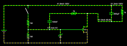
Finally, I was able to simulate exactly what I thought was happening. Simply connecting the battery positive lead to this schematic with assumed 150v causes a momentary spike up to 51v on the gate (or about 48v with 60v battery). this is more than 2x enough to kill a mosfet.

I removed the zener from the simulation intentionally as the simulation seems to suppress like it should in theory but that's not what happens in practice, not with zeners anyhow. Reading more about zeners, even though they are used for regulating the currents they are not effective in suppressing transients. For that, we'd need to use a TVS which is what I am planning to test next. If it works, that's great, however, it looks like the mosfet would be again compromised if the battery negative side gets disconnected (like BMS tripping for example). The gate again would go to crazy high voltage more than enough to kill it. See the second screenshot below. I'll experiment with TVS but I don't know if it's a good idea to always rely on them for a condition that we know is sure to occur.


1683593720955.png


1683593813088.png
 
Last edited:
BUT... The big problem is that there is a spike on the gate every time I connect battery (and there still a spark too)

Somewhere way back in the thread (or possibly a related one) someone explained why this happened. I can't remember what it was without looking it up. It seems like if you could clamp the gate to source voltage well enough you could keep things from blowing up. I have found that TVS diodes work much better than regular zener diodes, but I think there is more to it.
 
Just an update. TVS on the gate is a must to cover all possible scenarios such plugging in battery when the switch is on. That can cause spikes under some circumstances as shown above. Zeners are not able to handle transients. I've used the delayed gate charge approach at this time (as opposed to drain feedback) in a batch of controllers and it has worked reliably so far. I have also added TVS on all legs of the power stage gates as well to further boost robustness of the whole system.
 
.. er.. anybody ever just use a NTC thermister as a pre charge inrush limiter?
 
.. er.. anybody ever just use a NTC thermister as a pre charge inrush limiter?
NTCs might be OK for fairly low currents, but I don't think it would be practical for something that handles over 20A. They also have to get hot to work and would have some voltage drop.
 
Depends on the mosfet threshold used but simulation shows this with 2v threshold and 10uf +1M RC filter, at 100v.
About 3 sec. Red is the gate, yellow is current and green is voltage.

Using a thermistor sounds like throwing yet another variable. I don't see where it would add value in this case significant enough to bother. I'd rather be looking now to leverage the contactor to detect and prevent overcurrent conditions and deadly shorts through the phase mosfets. I am thinking of possibly adding some logic to diagnose the system before deciding whether to turn on the main battery power or not.

1687718558713.png
 
Back
Top