Adaptto Mini-E/Max-E Owner's Thread

Longshot said:
Hey maddin88, if you had to mount that controller interally near your battery, do you think it would help to put a fan between those small vertical ICB and a vent somewhere to cool it?
maybe it would help but i would not cut holes into the covers and mount such little screamer fan to it.. do you have no other options as example mounting a heatsink on outside of the frame and bolt the controller to it?

Longshot said:
:shock: Uhg, just looking at the stock wire makes me want to open it up and replace it. Nice work! What is your strategy for increasing power? What battery/volts will you start testing with?
Ohbse said:
That's beautiful work, well done. What's your intended power/usage to justify the upgrades?

probably i'll try up to 200A battery and 400A phase with MXUS 3T motor. this would be about 14kW with 20s battery.
generally i did this to make the controller more robust and all the more when i read Doc has blown a FET with a very high kV DD motor.
95% i drive not crazy just very normal, but its good to know i can make to bike going crazy if i want :twisted:

GreenRoad said:
good work maddin88
please take care on your copper wire - it could get bad if water comes into the wire - or salt - like in winter - if your are on the road.
If it is possible i never use pure copper wire - if tinned wires are avaiable.....
but its okay ----- only an tip.....

yes thats right. tinned copper is better for corrosion. thanks for the tip.
i thought of using shrink tube with glue for covering the bullets and wire insulation.. do you have other suggestions?
 
Hi madin88
As i told allready
If you rise the voltage and use an high rated KV Motor - this means more stress to the Mosfets.
in this case the settings should be very good and fine work - because the line to the border to the limits of the voltage capture of the mosfets are verry thin.
some little failure -bad hall signal or something like that - it depands on the controller - firmware could damage the mosfets.
This could go verry fast.
For that its good do to test with lower current - and raise the current step by step

To your wire
i would solder the End and the beginning of the wire - no crimp connection (depands on the plug you use)
normal water should be no problem - the problem is saltwater - now out of the street.
If you are getting salt inside - than you have lost.
I think you place the controller outside the bike - its better to place the controller in an dry area.... but i think you know this....
 
Doc has shown us what happens if we use high voltage in combination with low inductance and low resistance motor. I very appreciate all his work and (dyno) tests etc what he did. This is what makes ES such a good board. The testings and sharing of the results to other people. Im very thankful for this!

Now we know:

-> FET's could blow because of to high voltage spikes (also for the caps lifespan its not good)
-> additional caps at the input will smooth the spikes out which is also recommended by Adaptto

from jeka: http://electrotransport.ru/ussr/index.php?PHPSESSID=9917693pcorh60945b67035733&topic=18042.0

the current flows from the battery TO controller and FROM the controller to motor. this means:
more inductance between battery and controller -> not good for FET's
more inductance between controller and motor -> no problem

what does this tell us?

if we need to install longer wires we should do this on the motor side and not on the battery. if we cannot do it so, additional caps sould be installed as close ase possible to the contoller (if we push it hard)
 
Hello madin88
Iam with you - but the important thing is a "surge protection"
As i told: normaly the dielectric streng of the mosfets (voltage capacity) should be - the double amount of the battery voltage.
To operate in an safe area - thats normal if you build an industry controller

You guys are operation with differnt types of motors - some in extreme situation.
The most things are trying what is going ..... thats good and verry interesting for me....

To find out the right setting for Controller / Motor - is not only field testing.
You need to measure the voltage / current - with measuring instruments - to see what happens.

My own experience:
The concept of adaptto is good.
You need to conect the battery directly (with an fuse) to the controller, use the adaptto BMS.
a good stable - fix connection.
With this - your battery is the the load - lower for energy.
If you are getting voltage peaks - the battery should swallow this peak - but this take some time.
If you are placing caps to the controller - you could compare the wire lengh.
Thats why you should use Caps.
The important thing is the right choise of this caps - because if they are wrong, your are getting a additional Load for your battery - caps could get warm - damaged....

(If you are using an external BMS - not the Adaptto BMS - than it depands on the used Mosfets - because some mosfets have an integrated Voltage Protection, and "disconect" the battery)
I sometimes getting problems with motors, if i use an power supply unit, not an battery. If there are the caps to small, than i could measure voltages - in case of recuperate - more than i put inside the motor. That could be the double of the input Voltage!!!

In summary: a good electronic design , choise of Mosfets, Mosfets driver is important. The right settings for the controller also the firmware is important. If you are going to the limits - this things are getting more and more important.
 
GCinDC said:
[here cited from jeka] ...BMS has two channels: channel A (channel which is connected to all the expansion cards BMS), and the channel B, outputted to the contact pad.
Optional expansion cards can connect to both channel A, and to B, but care must be taken to address boards on one channel are not duplicated.
That is, if you have an extra charge with address 1, then you can connect it to an empty channel B, channel A and it can be connected only if it does not address the board 1.

Can anyone explain what "...channel B, outputted to the contact pad..." exactly mean? what and where are the "contact pads"? I would like to connect a second, external battery back and hope "channel B" might be useful !?
r
 
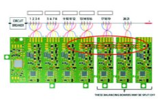
Hi Guys, I'm intending to hook up 10 multistar 4s 16000s to my max E I'm reasonably confident to do the 2p & series config but when it comes to plugging into the bms I can't seem to find info on the details i've highlighted in red. I'll be using the fifth board which is one of the snap off ones, in the image attached it shows a broken red jumper line between the boards?

Q: Does this mean to utilize these, additional connections need to be made by adding additional wiring?
 

Attachments

  • Graphic1.JPG
    Graphic1.JPG
    53.9 KB · Views: 3,885
not really madin88. I could mount the controller underneath like doc but then I will have wires everywhere. I want to make it look clean.
 
madin88 said:
Longshot said:
Hey maddin88, if you had to mount that controller interally near your battery, do you think it would help to put a fan between those small vertical ICB and a vent somewhere to cool it?
maybe it would help but i would not cut holes into the covers and mount such little screamer fan to it.. do you have no other options as example mounting a heatsink on outside of the frame and bolt the controller to it?

probably i'll try up to 200A battery and 400A phase with MXUS 3T motor. this would be about 14kW with 20s battery.
generally i did this to make the controller more robust and all the more when i read Doc has blown a FET with a very high kV DD motor.
95% i drive not crazy just very normal, but its good to know i can make to bike going crazy if i want :twisted:

yes thats right. tinned copper is better for corrosion. thanks for the tip.
i thought of using shrink tube with glue for covering the bullets and wire insulation.. do you have other suggestions?

I like where you are going with MXUS 3T! What advantage does the MXUS 3T have over the cromotor besides a couple of kg weight savings? It will heat up faster, no?
 
Jonboy said:
Hi Guys, I'm intending to hook up 10 multistar 4s 16000s to my max E I'm reasonably confident to do the 2p & series config but when it comes to plugging into the bms I can't seem to find info on the details i've highlighted in red. I'll be using the fifth board which is one of the snap off ones, in the image attached it shows a broken red jumper line between the boards?

Q: Does this mean to utilize these, additional connections need to be made by adding additional wiring?

I dont think those batteries will put out enough amps in a 2p config. They say 10C but really they are 2.5C. I really wish they were! I was looking at the 4s 10ah version. They would probably squeeze into my frame perfectly.

I think I read that you only need to jumper those break off ICBs if you break them off but Im not sure.
 
Longshot said:
Jonboy said:
Hi Guys, I'm intending to hook up 10 multistar 4s 16000s to my max E I'm reasonably confident to do the 2p & series config but when it comes to plugging into the bms I can't seem to find info on the details i've highlighted in red. I'll be using the fifth board which is one of the snap off ones, in the image attached it shows a broken red jumper line between the boards?

Q: Does this mean to utilize these, additional connections need to be made by adding additional wiring?

I dont think those batteries will put out enough amps in a 2p config. They say 10C but really they are 2.5C. I really wish they were! I was looking at the 4s 10ah version. They would probably squeeze into my frame perfectly.

I think I read that you only need to jumper those break off ICBs if you break them off but Im not sure.


Here ya go...

http://endless-sphere.com/forums/viewtopic.php?f=14&t=61672&p=1026874&hilit=multistar#p1026874
 
I connected everything up today apart from the motor as it's still away being built into a rim. I switched everything on but nothing happened. Does the motor need to be connected? If not then I have a problem. The battery connections are all good and I get what I expect (voltage) at the terminals going to the controller. The connector from the display to the controller doesn't look particularly straight but i have made sure it is correctly lined up. Any help would be much appreciated.
 
Just found a good sized heat-sink to attach to my Mini-E.
http://www.ebay.com.au/itm/Aavid-Thermalloy-Heat-Sink-7-5-C-W-MQ75-1-/121532652740?
$_12.JPG


What size are the Fet mount screw holes? I measured about 3mm, but not sure. Can anyone confirm?

Also, what size are the controller mounting holes. They seem to be about 4mm, but again, I'm not sure, can anyone confirm?

Cheers
 
Longshot said:
Longshot said:
Jonboy said:
Hi Guys, I'm intending to hook up 10 multistar 4s 16000s to my max E I'm reasonably confident to do the 2p & series config but when it comes to plugging into the bms I can't seem to find info on the details i've highlighted in red. I'll be using the fifth board which is one of the snap off ones, in the image attached it shows a broken red jumper line between the boards?

Q: Does this mean to utilize these, additional connections need to be made by adding additional wiring?

I dont think those batteries will put out enough amps in a 2p config. They say 10C but really they are 2.5C. I really wish they were! I was looking at the 4s 10ah version. They would probably squeeze into my frame perfectly.

I think I read that you only need to jumper those break off ICBs if you break them off but Im not sure.


Here ya go...

http://endless-sphere.com/forums/viewtopic.php?f=14&t=61672&p=1026874&hilit=multistar#p1026874

The tested the 16000 4s to really be 4C
 
Cowardlyduck said:
What size are the Fet mount screw holes? I measured about 3mm, but not sure. Can anyone confirm?

Also, what size are the controller mounting holes. They seem to be about 4mm, but again, I'm not sure, can anyone confirm?

The screws are M3 x 6mm coutersunk. holes are 3,2mm
 
Longshot said:
I like where you are going with MXUS 3T! What advantage does the MXUS 3T have over the cromotor besides a couple of kg weight savings? It will heat up faster, no?

it has higher kV so it will do more RPM at given voltage. yes it will heat up faster at same torque output than a Cromotor because of a few percent higher phase resistance, but i believe when cruising at 70-80kmh it will have same efficiency if not even more because i do not need flux weakening. maybe i need OVS 1 for this speed. on cromotor i need OVS 3. lets see how it turns out in practical.
 
madin88 said:
Longshot said:
I like where you are going with MXUS 3T! What advantage does the MXUS 3T have over the cromotor besides a couple of kg weight savings? It will heat up faster, no?

it has higher kV so it will do more RPM at given voltage. yes it will heat up faster at same torque output than a Cromotor because of a few percent higher phase resistance, but i believe when cruising at 70-80kmh it will have same efficiency if not even more because i do not need flux weakening. maybe i need OVS 1 for this speed. on cromotor i need OVS 3. lets see how it turns out in practical.


Maddin, i'm running the cromotor in 17" moto with a shinko sr241 3" wide (~23" out diameter) and without OVS i reach 75-80kmh and with OVS 3 i reach almost 105km/h.
I was getting more or less the same results of you after the autodetect process, but after that i have done the manual tunning of the motor according with the manual and i've start to achive greater speeds. And i still think that my motor don't have the fine tunning process at 100%.
 
I dont think those batteries will put out enough amps in a 2p config. They say 10C but really they are 2.5C. I really wish they were! I was looking at the 4s 10ah version. They would probably squeeze into my frame perfectly.

I think I read that you only need to jumper those break off ICBs if you break them off but Im not sure.[/quote]


Here ya go...

http://endless-sphere.com/forums/viewtopic.php?f=14&t=61672&p=1026874&hilit=multistar#p1026874[/quote]

The tested the 16000 4s to really be 4C[/quote]


Hey longshot.. time for a re-think! I'd not seen that. 4c is crappy.. the setup i was thinking would be 10c / 20c burst at 4c lands up @

C=64amps continuous X 74V nominal = 4736W... that makes for a sleepy raptor .. :-( What a shame, It's plan B then.. !


Quick edit @ 20s 2p (16000 4s) would that work out at 9472W Max? I'm happy at 6-7kw


I Think the "C" rating remains the same but the max safe wattage would be doubled & below circa 9472W

Could one of you clever folk confirm this?
 
striker54 said:
Maddin, i'm running the cromotor in 17" moto with a shinko sr241 3" wide (~23" out diameter) and without OVS i reach 75-80kmh and with OVS 3 i reach almost 105km/h.
I was getting more or less the same results of you after the autodetect process, but after that i have done the manual tunning of the motor according with the manual and i've start to achive greater speeds. And i still think that my motor don't have the fine tunning process at 100%.

what voltage do you have?
could you tell us what settings you now use after manual tuning?
don't fix to much on the speed statements because i don't had them exactly in mind. you have right they are a bit to low and cromotor will do about 80-90kmh or more with my setup at OVS 3.
but MXUS 12kV will be faster at 20s and thats what it is about. it should not need that high OVS levels to achieve same speed as with cromotor setup.
 
Can anyone share some set-up numbers for Crystalyte H4080 (modified- replacement Bomber motor spec'd) to Mini-E? I installed the Mini a week ago and couldn't get it to do an Autodetect, "Halls 2" error code- "!Halls!" on main screen too. I tried all 6 wire combinations and no go? So yesterday I finally had some time to play with it, after some manual "tuning" (uhhh, guessing) the motor runs better and got the "!Halls!" error off the main screen, but still get "Halls 2" error in Autodetect and still can only run sensorless!? Don't really know what all the settings do either, but "Angle Corr" seems kinda important? Has anyone been able to "Autodetect" with a H4080?

I know I'm new here, I asked other questions before and they were ignored, but I schooled myself and worked it out correctly...... just figured I'd give this a shot, if not, I'm sure after another week I'll get "Tits Sumo" running hot myself......

Thanks!,
SDog
 
madin88 said:
what voltage do you have?
could you tell us what settings you now use after manual tuning?
don't fix to much on the speed statements because i don't had them exactly in mind. you have right they are a bit to low and cromotor will do about 80-90kmh or more with my setup at OVS 3.
but MXUS 12kV will be faster at 20s and thats what it is about. it should not need that high OVS levels to achieve same speed as with cromotor setup.

I'm running 22s Lipo. Ok, I didn't think in that. Maybe the diference is in the voltage, but i can assure that there is a big diference in performance between running with the autodetect settings and after doing the manual tunning. I will post the settings when I get at home, but I think that the settings from one motor aren't good for other motor even when they are same model, because there will be always small differences in the production of the motors.
 
skWarDog said:
Can anyone share some set-up numbers for Crystalyte H4080 (modified- replacement Bomber motor spec'd) to Mini-E? I installed the Mini a week ago and couldn't get it to do an Autodetect, "Halls 2" error code- "!Halls!" on main screen too. I tried all 6 wire combinations and no go? So yesterday I finally had some time to play with it, after some manual "tuning" (uhhh, guessing) the motor runs better and got the "!Halls!" error off the main screen, but still get "Halls 2" error in Autodetect and still can only run sensorless!? Don't really know what all the settings do either, but "Angle Corr" seems kinda important? Has anyone been able to "Autodetect" with a H4080?

I know I'm new here, I asked other questions before and they were ignored, but I schooled myself and worked it out correctly...... just figured I'd give this a shot, if not, I'm sure after another week I'll get "Tits Sumo" running hot myself......

Thanks!,
SDog
Hey SDog, your not the only one who will be attempting this. I also have the HS4080 I will be running on my Fighter when I finally get around to getting everything up and running. At the moment I'm still modifying it for forced air cooling. :twisted:
http://endless-sphere.com/forums/viewtopic.php?f=30&t=56965&start=100#p1009838
P1070421.jpg


FYI, the 4080 is not used on the Bomber, just the Fighter. I think the Bomber uses the 5403 motor normally.

Cheers
 
Skwardog, this is my settings for the 4065 which shouldn't be too far off. I too had issues with auto detect in terms of rough running (it had something like 30 degrees to start with) until adjusted but no hall issues once all the wires/plug were sorted. If you are having hall issues you may have issues with you plug or wiring.

 
striker54 said:
I'm running 22s Lipo. Ok, I didn't think in that. Maybe the diference is in the voltage, but i can assure that there is a big diference in performance between running with the autodetect settings and after doing the manual tunning. I will post the settings when I get at home, but I think that the settings from one motor aren't good for other motor even when they are same model, because there will be always small differences in the production of the motors.

LiPo has flatter discharge curve and higher nominal voltage and this will make a noticeable difference in speed.
i also do not use all autodetect settings. indtiming and anglecorr i let as is is, but PWR timting i changed..
waiting for your post
 
Back
Top