Adding LifePo4 to BionX System

Konnections said:
Thanks, Ken. One further question: Can the Bionx charger be used on LiMn or Lipo batteries? It would be easy enough to hookup a female XLR plug on the charging wires of the battery...of course that would mean charging the Bionx and the 2nd battery separately, but it would save the cost of a second charger.
Terry:

Yes, a Bionx charger can be use on Bionx battery, LiMn or LiPo. But it better to be the other way around to use standard LiPo charger (42.5volt) to charge both LiPo, Bionx battery, and possible LiFePo4 There are two issues here:

1.) Bionx charge port use 4 pin connector, most of standard lithium charger use 3 pin. If you want to use a single charge on both batteries, you will need to make 3 to 4 pin XLR adapter just for the Bionx battery.

2.) In order for Bionx to get and claim to have 800 cycle life on Bionx battery, to get that extra life of the battery, Bionx under charge the battery (max around 41 or 42 volt), and increase to low cut voltage to 31 volt instead of 29v. So if you take regular standard LiPo charger, you will bring up the voltage to its maximum.

In term of LiFePO4 battery, the fully charge voltge should be 43.5v, so you don't want to use a true LiFePo4 charger on a LiMn or Lipo battery. In this case, if you are mixing LiFePo4 and Bionx and LiPo, then you should use regular LiPo charger 42.5v, this will allow to use a single charger on all of the batteries type.

Ken
 
Ken,

Are you offering the additional battery package (as pictured in a previous post in this thread) generally? If so, at what price and what battery capacity?

It wouldn't be too hard to rig it up oneself, but if you are offering a well tailored pack at a good price, some (including myself), might be interested. I'd have to factor in delivery charges to Australia, but others more local to you might see it as even more attractive with the lower delivery charges or the ability to pick up.
 
Wow, lotta work: Built the 7s5p pack of 2.2Ah Blue Lipos, and charging harnass so I can balance w/ DB9 connector, and discharge w/ BM6 buzzer.
2010-08-06 23.02.46.jpg
And here's the very first ride:
[youtube]eHQIdPooc3Y[/youtube]
Gotta say I'm pretty disappointed that I don't have more power with two fresh packs. I guess I was thinking a 29V lipo would power it up hills... Not even sure I noticed any improvement. True, I hadn't cycled the lipos yet, but I'd be surprised if that matters much.

She'll have a lot more range, but that wasn't really the goal.

Anyone interested in buying the 7s5p pack w/ charging & disharge harness, let me know! It's for the 24V system only. Not sure I'll sell it but am thinking about it right now...

Oh yeah, and there's a real long hookup cable so it could be mounted on the trailer, so she could use it just with that...

Wait, I wonder if it'd perform better the ericslai way, rather than via the charge port...
 
What an interesting thread, but so confusing. It looks like some have had success with an extra battery. I am seriously thinking of buying a Ping 36v 20 ah lifepo4 battery and wire it to the charge port. What are my chances of this simple mod working? Can anyone who has done this successfully please share. There are a lot Bionx owners hoping for this mod!
Thanks Jim
 
jocoman said:
What an interesting thread, but so confusing. It looks like some have had success with an extra battery. I am seriously thinking of buying a Ping 36v 20 ah lifepo4 battery and wire it to the charge port. What are my chances of this simple mod working? Can anyone who has done this successfully please share. There are a lot Bionx owners hoping for this mod!
Thanks Jim
Hey Jim,

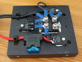
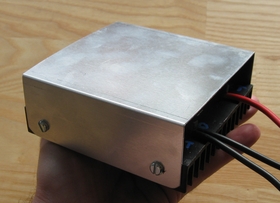
I'm convinced this will work. I've done it, but with LiPo battery. Ken did it for a customer (bottom pg 2). Canis, in first post, quotes someone from V is for Voltage forum who did it. All of us connected additional battery via the charge port.

It's advised, however, to connect the Lifepo4 towards the end of the BionX battery's charge. Why? It's hard to explain! I'm no EE, but I think I understand it a bit.

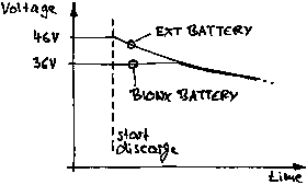
First of all, everyone always says NOT to parallel batteries of different chemistries (ie, LiMn and LiFePo4). Why? One reason is they have different charge/discharge characteristics. Your BionX LiMn pack is made up of cells that charge to 4.2V and discharge to 2.9V (but to live longer, Bionx only let's them discharge to 3.1V, according to Ken). So your so called '36 volt' Bionx battery is charged up to 42 volts (10 cells in series x 4.2V = 42V). As soon as you start out, the voltage quickly drops to 39V or so, and then as you use it steadily decreases to 31V. To my understanding, it's called 36 volts because that's the average voltage under load for the range of the pack. Now the Ping pack is different. His '36V' pack is made up of 12 cells in series. The charger charges them up to 45-46V, so 3.84 per cell (12 cells x 3.84V = 46V). That's a lot higher than your BionX pack, but once under load from the motor, the voltage drops to an average working voltage of ~3.3V per cell, or 39V. (My numbers may be off, but it's the general idea). The discharge curve will be flatter than the BionX. I found a graph done by ebikes.ca that illustrates the voltages under 10A load for different types of 36V batteries. Note the Green (LiFe) and blue (LiMn) curves:
10A_Disch_Curves.gif

I'm sure the LiMn and Life(po4?)ezee packs are different than the BionX and Ping packs, but I think the graph describes the differing characteristics.

What's the point of this? Well, once you connect the two batteries in parallel and close the circuit, they will try to balance, and if one pack has a much lower charge (voltage), it's dangerous if the full battery tries to charge it too fast. The components in between may be subjected to too much current... So when is the best time to connect them? Or, when are the charges most similar? I'm not sure! But what I've gathered from other posts on the subject is that:
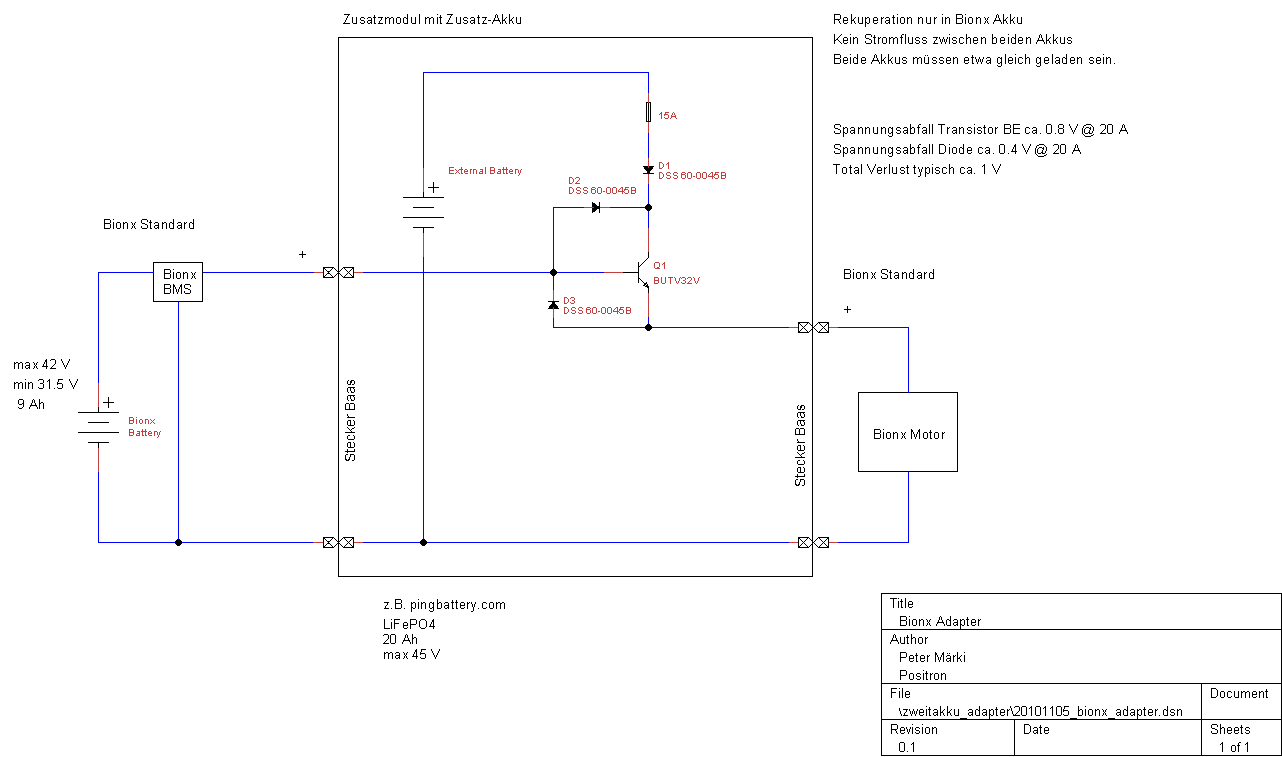
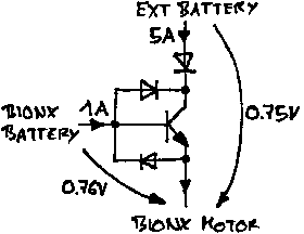
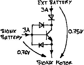
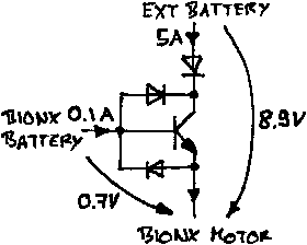
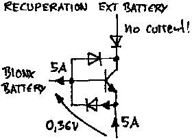
- The lifepo4 battery is isolated, so cannot be charged by the BionX battery, or be subjected to the regen current. Current can't go upstream to the lifepo4... (great news!)
- The BionX LiMn cells don't do anything funky when overcharged, in case that were to happen. (liveforphysics)
- When connected, the lifepo4 will charge the LiMn pack, but how much and how fast? The Ping puts out max continuous what, 20A? That would be too much to charge the BionX! But presumably the lifepo4 will also deliver current to the load (motor)? The motor probably doesn't care when the current comes from. You just want to make sure the load on the lifepo4 is not so much as to shorten its lifespan... I think of a bucket of water (bionx battery) with a hole or tube in letting water out (current to the motor). Then attach a second bucket by a one way valve to the first bucket. The level of the water (voltage/charge) in the buckets will try to balance... The current to the motor will stay the same.

I could be completely wrong, and I hope someone corrects me! But this is how I understand it...

Will it work? Yes, it will work? Will there be sparks? I seriously doubt it. I've got a ping pack that i could test to be sure (for my 24V system)...

But one thing you could do is, before your commute, set your BionX console to diagnostic mode and during your ride, note the changes in voltage from start to finish, uphill and downhill on regen to get a sense of how it fluctuates). There's no harm at all in riding like this. Here's the page from the manual:
BIONXDIAGNOSIC


Canis, have you come closer to doing this?
 
FYI
GCinDC said:
Hi Ping,

A friend has a BionX kit with a 36V LiMn battery of Sony cells. It's 10s, so charges up to 42V. But he wants to add a battery to extend his range after the BionX battery is mostly discharged.

I suggested he use your 36V20ah pack to plug in to the (isolated) BionX charge port (I've tested, it works) when the BionX battery is almost used up. During operation, if the voltage of the BionX pack is lower, your pack will charge it. But if the motor is pulling 5-10Amps, can your fresh pack deliver the current?

What do you think?

I've been trying to find discharge curves of your lifepo4 cells at different amps but can't find any. Can you email me sample discharge graphs, at say 5Amps, 10Amps, etc?

If your charge voltage for the 36V pack is 45-46, then each cell is charged to max 3.83? What then is the working range? 3.3V - 3.0V?

Thanks for your help!!

Greg

Ping said:
Hi Greg,

Sorry for the late reply. I just saw this email in the spam folder.

It’s really a good and innovative idea to use other battery packs on BionX systems.

If the motor is pulling 5-10amps, it should be pulling from the bionx battery. Of course, our 36v20ah pack can output 10amps without any problem, but I’m not sure the charger port of Bionx can withstand 10amps.

If what you concerned is the voltage sag at 10amps, please don’t worry. Voltage sag at 10amps of the 20ah pack is only a little. Actually, at the same time, the Bionx battery will also have voltage sag.

LiFePO4 has virtual voltage. When it’s doing nothing, voltage is about 3.3v. When fully charged, about 3.7-3.8v. When deeply discharged, about 2.1-2.5v. Its working voltage is 3.0v. That’s why we use 12s cells in the 36v pack. But if working current is low, its voltage will be higher than 3.0v.

Best regards,

Ping
GCinDC said:
thank you!

do you mind if i post your reply on a forum? do you know endless-sphere?

there is a topic where people are asking if it's possible to use lifepo4 to extend the bionx... i think they would like to see your response!

please let me know.

thanks,

greg
Ping said:
Hi Greg,

No, I don’t mind you post my reply to endless-sphere. Yes, I know the forum and know many people on it.

Just a moment ago, I thought that if bionx is drawing 5-10amps or even higher, the current through the charging port couldn’t be as same as the controller. It should depend on the BMS in bionx, voltage and resistor of the battery in bionx.

We will do a test for you on Monday. To discharge a v2.5 36v20ah pack at 10amps, then to see how many minutes later its voltage drops to 37v (the voltage 10s LiMn is completely drained).

Best regards,

Ping
 
GCinDC said:
Canis, have you come closer to doing this?

No, not yet, sorry to report. It's just a matter of time, and money, of course.

Just on another note, I have been pleasantly surprised by the life of my existing lone BionX battery. Although I haven't made a determined effort to exhaust it, so far in the natural course of my trips, I haven't depleted it. Of course, on my longer trips of 50k's plus, I have rationed out usage so as to make it last as long as possible, but it is clear that the last bar has a lot more charge in it than other bars. While the first bar disappears fairly quickly from the console reflecting battery usage, when that last bar disappears, there is still a lot of km's left in the battery yet. The last bar, ie. no bars, seems to come close to the first 3 or 4 bars.
 
Hi Greg,

Attach a simple discharge curve of a brand new v2.5 36v10ah pack (posted w/ permission). We did it last week.

Best regards,

Ping
here's the voltage curve under a 10Ah (1C) load. astonishing flat!
V2.5 36V10Ah 1C Discharge (1).jpg
 
Hi guys, I'm very interested in adding a second battery through the XLR connector, but using a diode in serie in order to avoid regen in the 2nd battery and continuous balancing.
In the BionX pack, I observed that they have connected the XLR connector to the battery through a thermistor (seems to be the same thermistor than on the image at the beginning of this post). And they say in the manual that charging current should not be higher than 2.3 or 2.7A... Does anybody know the specification of this thermistor? Would it limit the charging current and make impossible to add a second battery equal to the 1st one?

Thanks for help.

PS: Bionx 500W, 1000km/month
 
Hi guys

I wrote an proposal on how to ad an LiFePo4 battery to bionx using several diodes an an power transistor.

Ideas:
No change of the Bionx system. Circuitry is connectet between the power connector to the motor.
Simply adding an second battery, discarge of both batterys together. Works best when both batterys are fully charged. Otherwise you have more loss.
External battery can be carried on the luggage carrier (near to the connector to the motor).
No current flowing between bionx battery and external battery even when they have different voltages.
External battery can have higher voltage than bionx (46 V for example). Voltage at the motor will neber go higher than voltage of bionx battery. (possibly the motor is protectet against high voltage)
Motor-Voltage is nearly equal bionx-battery voltage. When bionx battery is removed or console is switched off, no power goes to the motor. I think this is importent to meet regulations, otherwise bionx wuldnt have built the possibility to switch the motorvoltage off.
When bionx is switched of, no loss at all.
Recuperation: current only goes into bionx battery, no current goes to the external battery which could possibly destroi the battery manager of the external battery.
Voltage drop of about 1 V (guess) because of circuitry. I'll measure it exactly when i built it.
1 V will cause about 3 % loss of the system. I think this is ok considering the advantages.
Parts will cost about 45 USD.

Proposal in german whith schematic and part descriptions:
http://www.positron.ch/peter/album/20101111_bionx_external_battery

I will build it about in spring (march 2011).

What do you think? Do you see faults?
Every feedback is welcome.

Peter
 
Hi GCinDC

No, i did not mean the XLR Connector. The XLR is not made for high current use (i think so). The XLR is connectet to the Bionx Battery Manager which assumedly doesnt survive high current flow from the external battery. I had ideas to use the spare XLR pin, but then you have to modify the Bionx battery which i dont like.

I proposed to insert my circuitry into the power cable to the motor. There is a 2 pole connector.
http://www.positron.ch/peter/album/20100817_bionx/images/20100818_083857_.jpg

Peter
 
maerki said:
I proposed to insert my circuitry into the power cable to the motor. There is a 2 pole connector.
I was thinking, wait is the BionX brushed? Where are the phase wires?

Then I remembered that the controller is inside the motor! Docbass has great pictures but you must have seen them... I've always wondered what functions were separate (or shared) on the board in the battery and the controller...

Anyway, I officially have no idea what will happen if you connect there!
 
maerki said:
Hi GCinDC

No, i did not mean the XLR Connector. The XLR is not made for high current use (i think so). The XLR is connectet to the Bionx Battery Manager which assumedly doesnt survive high current flow from the external battery. I had ideas to use the spare XLR pin, but then you have to modify the Bionx battery which i dont like.

I proposed to insert my circuitry into the power cable to the motor. There is a 2 pole connector.
http://www.positron.ch/peter/album/20100817_bionx/images/20100818_083857_.jpg

Peter
Peter:

If you connect 2nd battery through the 2pin trailer connector, when regen happen, the current will flow back to both batteries. You can hookup a CycleAnlyst in the same way, you will see negative amp. It is not a bad idea, assuming that 2nd battery have over current protection. When over current occur, your 2nd battery BMS will shut down, the current load will flow back to first original battery to take the load. This will avoid possible blow up on the circuity board.

Ken
 
Hi itselectric

Here you can find the shematic of my proposal:

http://www.positron.ch/peter/album/20101111_bionx_external_battery/images/schema_g.gif

When regen happen, the current will flow through D3 into the bionx battery. The external battery will never be carged because of D1.

Normaly, with bionx assist, the current of the bionx battery will flow through BE of the transistor, D1 from the external battery and depending of the voltage of both batterys as well through D2.
When the voltage of the external battery is higher than the voltage of the bionx battery, D2 wont conduct. The voltage of the motor will be about 0.6 V lower than the voltage of the bionx battery and most of the current will come from the external battery througt D1 and CE of the transistor. The external battery will be emptied until the voltages of the batteries are nearly equal. After that point, both batterys will be discarged together.
The transistor is ver

Peter
 
I built the circuitry now:
Schematic:
schema_g.gif

20101113_144200_.jpg

20101113_163031_.jpg


First measurements in my office:

Regular discarge of both batterys.
External battery 5 A, bionx battery 1 A.
regular_1_5.png

External battery 3 A, bionx battery 3 A.
regular_3_3.png


Discarge with external battery is charged much higher:
regular_.1_5.png


Recuperation:
recuperation.png


Example: External battery is charged much higher than bionx battery: (its better to charge them both but it can happen like this)
discarge.png


I guess with high currents, 20 A for example, the voltage drop wont exceed 1 V.

Here you can find the proposal in german. http://www.positron.ch/peter/album/20101111_bionx_external_battery

Peter
 
maerki said:
Hi itselectric

Here you can find the shematic of my proposal:

http://www.positron.ch/peter/album/20101111_bionx_external_battery/images/schema_g.gif

When regen happen, the current will flow through D3 into the bionx battery. The external battery will never be carged because of D1.

Normaly, with bionx assist, the current of the bionx battery will flow through BE of the transistor, D1 from the external battery and depending of the voltage of both batterys as well through D2.
When the voltage of the external battery is higher than the voltage of the bionx battery, D2 wont conduct. The voltage of the motor will be about 0.6 V lower than the voltage of the bionx battery and most of the current will come from the external battery througt D1 and CE of the transistor. The external battery will be emptied until the voltages of the batteries are nearly equal. After that point, both batterys will be discarged together.
The transistor is ver

Peter
Peter:

I am not an electrical engineer, so I don't want to say that I fully understand your design. If you are design this to block the regen current and balance the voltage between the two batteries. And you happen to use Ping battery, I believe it is unnecessary. Ping battery does not accept reverse current or regen. As long as you have the original bionx battery to take the reverse current or regen, you don't need the extra stuff with a junction wire at the trailer connection. However, if you don't have the original bionx battery, this design is need to protection over current.

Ken
 
Ken:
I am not an electrical engineer, so I don't want to say that I fully understand your design.

I am, i do :)

And you happen to use Ping battery, I believe it is unnecessary. Ping battery does not accept reverse current or regen.

I want to be able to use any battery with similar voltage than bionx.

I want to use my bike with the original bionx battery and an attached external battery. I want do discarge both batterys together; this has the advantage of a lower current in both batterys.
With my proposal, the regen current flows into the bionx battery, not into the external battery. Thats exactly the idea behind. I dont want to use an external battery only.
With diode D1 i prevent current flowing into the external battery.

If you just attach an external battery without diodes ... you can destroy things.
If you use two diodes, one from each battery, you cant handle the regen current. And you cant switch of the voltage on the motor-plug (as is in original bionx configuration when you switch controller off). (there have been such proposals earlier in this forum)
With my proposal you can solve those problems.

As long as you have the original bionx battery to take the reverse current or regen, you don't need the extra stuff with a junction wire at the trailer connection. However, if you don't have the original bionx battery, this design is need to protection over current.

Yes, i have the original bionx battery attached. I inject the energy from the external battery at the junction to the motor. Instead of just attach the battery, in insert my circuitry to protect the batterys, the bionx battery and the motor.

Peter
 
Recognizing the versatility that you are trying to build into your design, I wonder if many users wouldn't be better served by (1) ensuring that they select a battery that is charged to a final voltage no higher than that of the internal Bionx battery (actually, no higher than the voltage of the internal battery plus the voltage drop across a single diode), (2) using a single diode to block current flowing into the external battery (if it doesn't already include a BMS that provides that function), and (3) either using a switch to cut off power from the external battery pack or connecting it internally so it is controlled through the same relay as the internal battery.

I ask because your design requires all current flowing to the motor to pass through across 2 junctions, one each in a diode and the transistor. With the voltage drops you're showing, that can be a significant amount of power dissipated as heat. You do have proper heatsinking in your prototype, but wouldn't it be best to minimize the amount of energy that must be managed as heat in the first place? With the simpler approach, only the current flowing from the external battery is exposed to any voltage drop at all, and that current must cross only one junction rather than 2.

I do think yours is a creative approach, and will follow your work with interest (especially as the battery in my PL-350 ages!)

Charlie
http://ElectricCyclist.com
 
Hello! I'm new here.....

I just got a Catrike with a PL-350 Bionx.

Although I built an AC Pusher Trailer last summer (3 phase AC inverter duty motor produce "Hold On For Your Life" Torque)
The Bionx system is a nice system for a carefree work out. My wife giggled when she tried my trike with the Bionx. Now she
wants one on her trike! :)

I can go about 70km on a charge with head winds and some hills. If you ride a trike, and your friend is on a racer bike, draft him a about 6 inches away
from his rear tire, and in a head wind, he will nearly pull you along with little effort! :) A little dangerous? Yes! Exhilarating? Yes! Know the guy in front of you and keep a ready brake waiting! :)

So what happened to this thread? It just came to a screeching halt!

I'd like to extend my range. And once my wife get's her Bionx, then we will be able to go for extended explorations/picnics! :)

Does Peters circuit work?
Do you just need diodes?
Will anyone help?

Thank you! Tommy L sends....

My AC pusher trailer! Yes Yes Yes, 150lbs (70 Kg) Don't laugh too hard.
But it does go 35km on a charge and the torque is unreal!
54km Top Speed - 43km cruise

http://www.youtube.com/watch?v=Q1qTc4sjORY
 
Hi Peter and all,

I am new here too. I ordered recently a BionX set as a birthday gift to my partner. I hope she will like it. I like the way it is done and it works. In the meantime I am trying to learn about BionX drive as much as possible. I found this forum very informative. Let me share with you some ideas coming to my mind.

I am contemplating how to connect an external battery (batteries) to the BionX drive. Direct connection discussed here looks appealing, one would say it minimizes losses. However, usage of different batteries leads to an unceasing charge "spillover" between parallel branches. Rechargeable battery does not return back all received charge, but not insignificant part turns into other forms like a heat, chemical degradation etc. Would you think that a battery pack built from LiFePO4 branches of diverse capacity cells will work efficiently? Probably not.

It is a good practice to connect different batteries using a balancer circuit. The simplest implementation is a "diode OR" circuit. However, it does not work for the regenerative charging. Fortunately, we can exclude regenerative charging of the external battery. I like a brilliant simplicity of your idea, Peter, using a bipolar transistor with diodes. It works well when both batteries are in a close state of charge. Suitable transistor is very expensive (30EUR/34USD), diode is about 3.5EUR (4USD), but you don't need much more. There are some voltage losses, but more importantly, different voltage and/or internal battery resistance is equalized after the weaker battery. Starting with your circuit, Peter, I replaced the transistor with another diode and got following circuit:

Untitled4a.png
It isolates weaker battery till the stronger battery reaches the voltage of the weaker one, and charges back with regenerative braking only the internal battery. If there is a battery voltage discrepancy or fluctuation, the circuit just stops discharging the lower voltage battery till the moment of equalization.

The main trouble with the circuit is that even using Schotky diodes there is some voltage drop (loss) between the battery and the motor. Discharge losses are twice the diode forward voltage (about 2 * 0.6V = 1.2V). Regenerative recharge losses are just single forward voltage (about 0.6V). Suitable Schotky diodes (high forward current, high reverse voltage, low forward voltage) are not many, and are expensive. Luckily, there is so called "ideal diode circuit", and even better, there are "Ideal Diode Controllers", which are simplifying design of the circuit. The Linear Technology's "High Voltage Ideal Diode Controller" LTC4357 (see http://www.linear.com/product/LTC4357) seems to be perfect for this use. It contains everything necessary to create an "almost ideal diode". Here is an example of two ORing diodes connecting two 48V sources to a single load:

Untitled6.png
For the purpose of use in the above mentioned diode circuit will be ideal a common, relatively cheap and easily obtainable MOSFET transistor IRFP4110 (100V 120A 370W 4mOhm). Yes, when switched on, this MOSFET transistor has just 4mOhm of resistance, about one meter (yard) of AWG 11 (4.2mm2) wire - not bad, isn't it? 50A will cause a loss of just 0.2V, which means that the package will have to dissipate just 10W. A more common 20A will cause a loss of 0.08V, heating with just 1.6W. LTC4357 is about 5EUR (6USD), IRFP4110 is about 4 EUR (5USD), sum times four is equal to a total of 36EUR (44USD). I can imagine a realization of the complete circuit on a single PCB of a palm size. The other solution could be an "almost ideal diode module" - a small PCB (30 x 30mm, 1 1/4"x 1 1/4") in a style similar to the SOT227 package:

images


, each containing either one or two diodes, allowing an easy custom utilization and also easy replacement of a broken module in case of a failure. In either case, I like Peter's construction inserting this circuit to the BionX system at the place of the motor connector. Perhaps a whole circuit could be placed in a suitable slim Al "jaeckel" acting as a cooler, with corresponding connectors in stoppers on both ends. This could be placed bellow bottom tube of the rear part of the bike frame in a holder. From the back will be connected the hub motor, and from the front the BiomX's battery cable. Other cable will run out from the front to the external battery. Well, better to stop now.

What do you think? I know, all this is just a silly theory, and perhaps somewhere is a trap.

Respectfully

Martin
 
Back
Top