Advice - 18 FET Controller Mods for More Power

gomyles

1 W
Joined
Nov 13, 2019
Messages
50
Hey guys,

Here is my controller;

20210108-211419.jpg

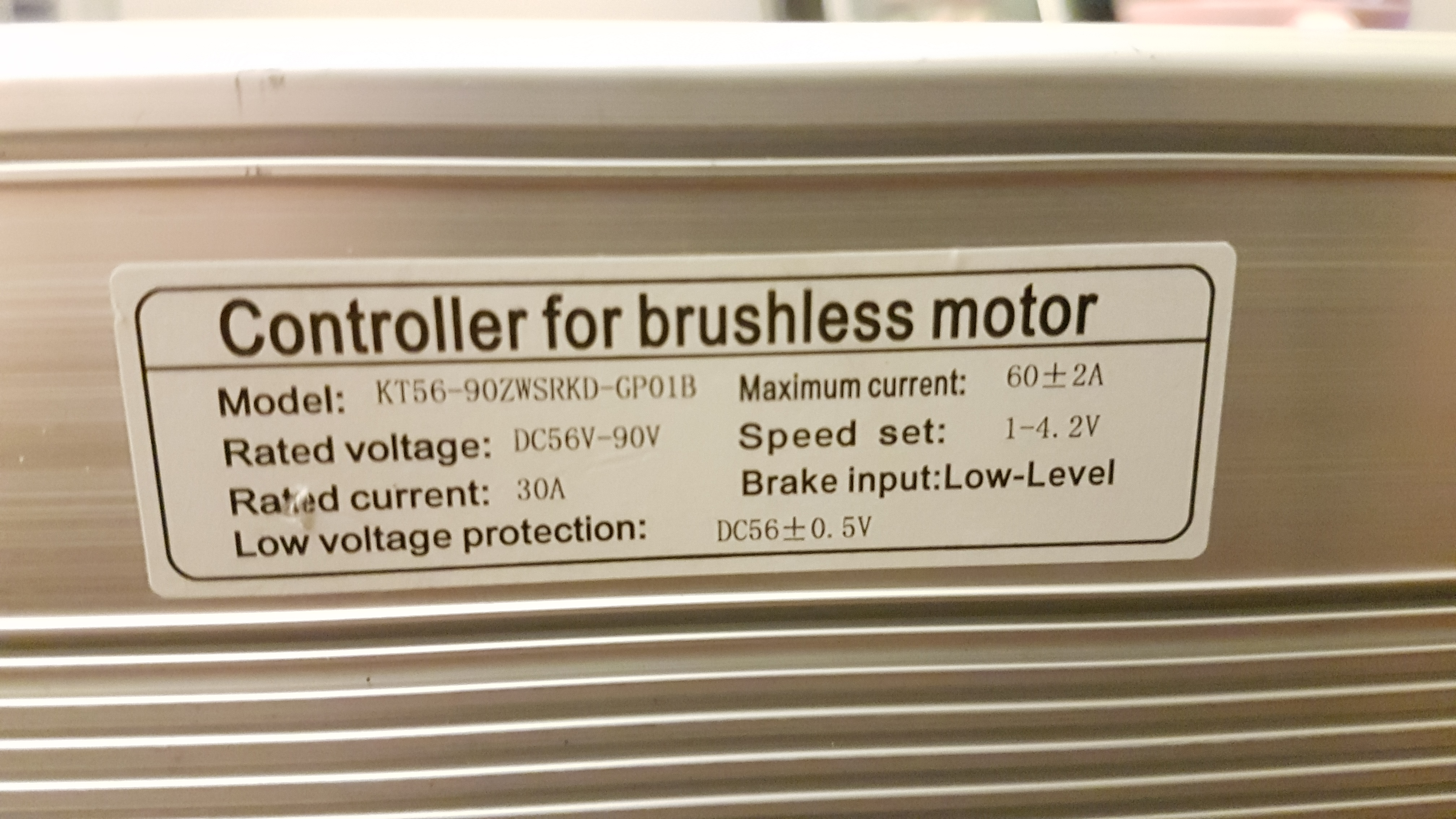
https://i.ibb.co/5TJ582k/20210108-211419.jpg

It is a pretty big controller and am hoping to increase current to about 120A from the original 60.

20210108-211435.jpg

https://i.ibb.co/n09rzM5/20210108-211435.jpg

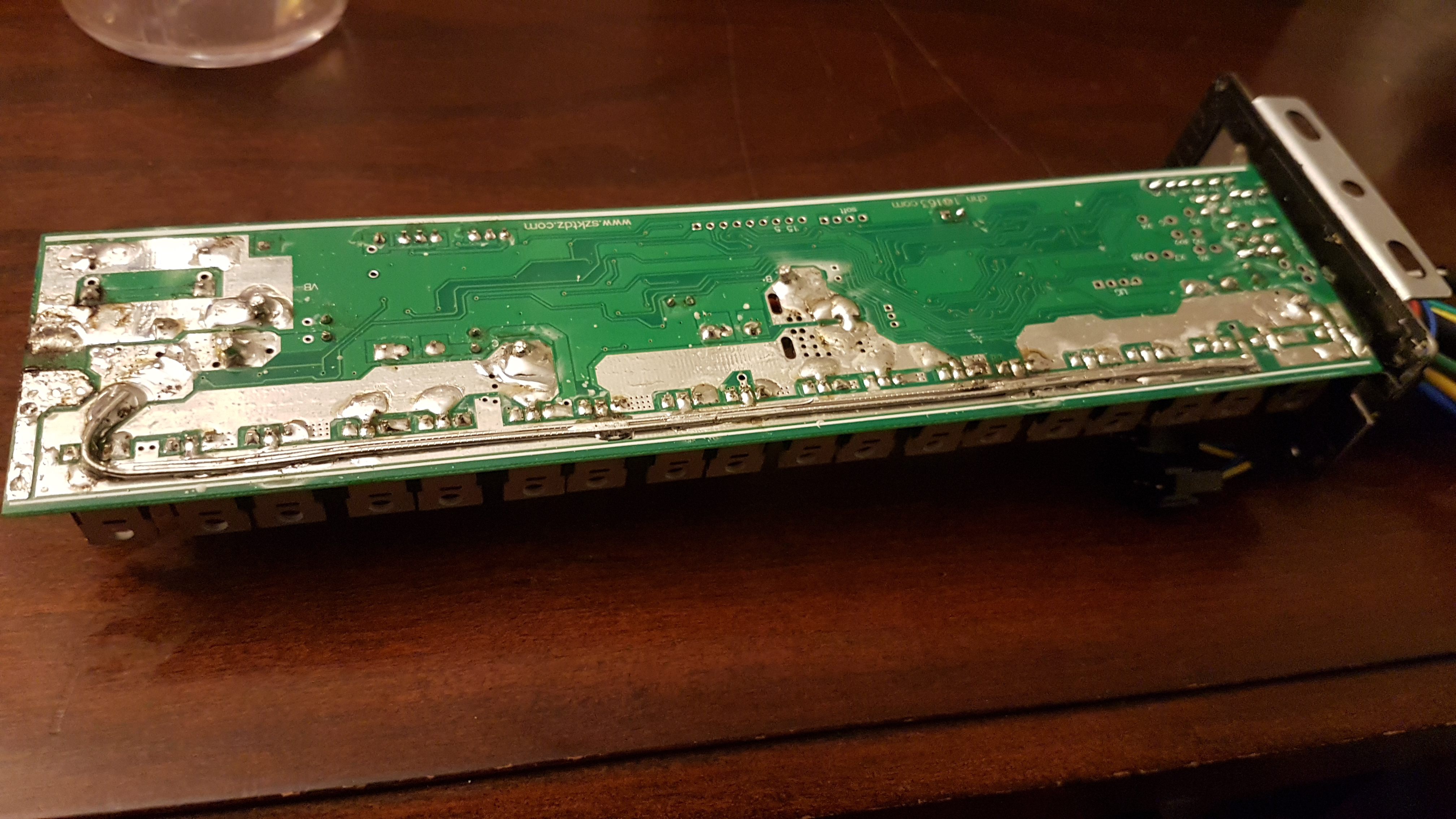
My understanding is to "beef the traces" which I believe means anything underneath that has is connects the fets to the phase wires and battery terminals underneath, add solder and/or copper wire? It really looks like there's a lot of room to add solder here, it looks pretty bare.

20210108-211547.jpg

https://i.ibb.co/zx5FNQJ/20210108-211547.jpg
20210108-211910.jpg

https://i.ibb.co/SV4m1H8/20210108-211910.jpg


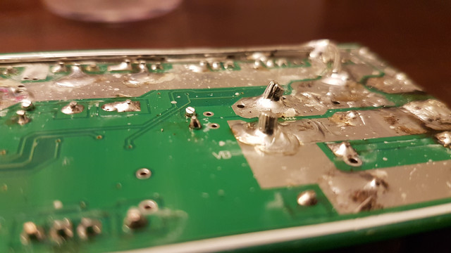
Also, add solder to the shunt, here is my current solder job to the shunt, how does this look right now, for 120A ? (I know it will have to be tested but just want to see)

20210108-211506.jpg

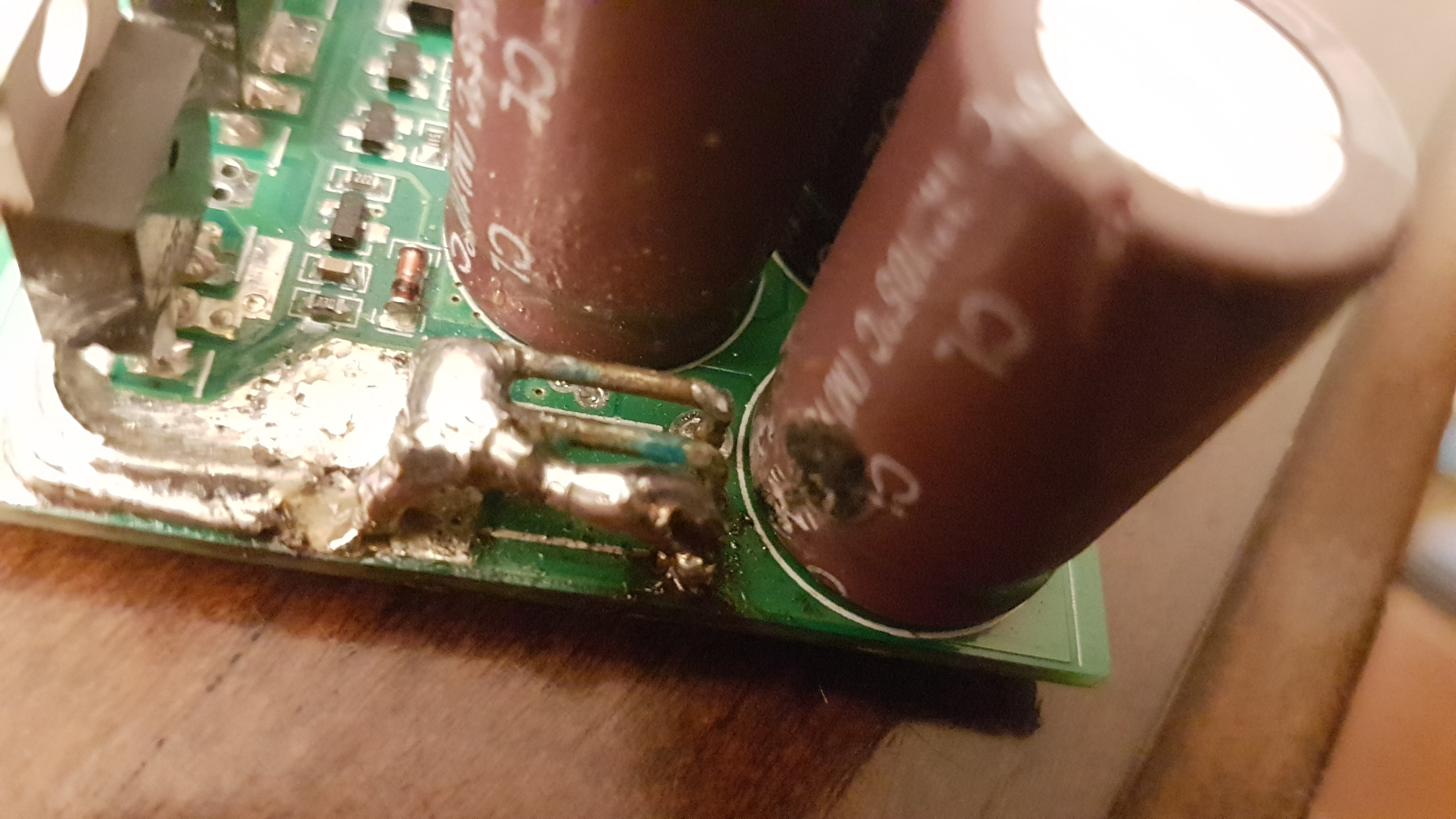
https://i.ibb.co/GskX3q1/20210108-211506.jpg

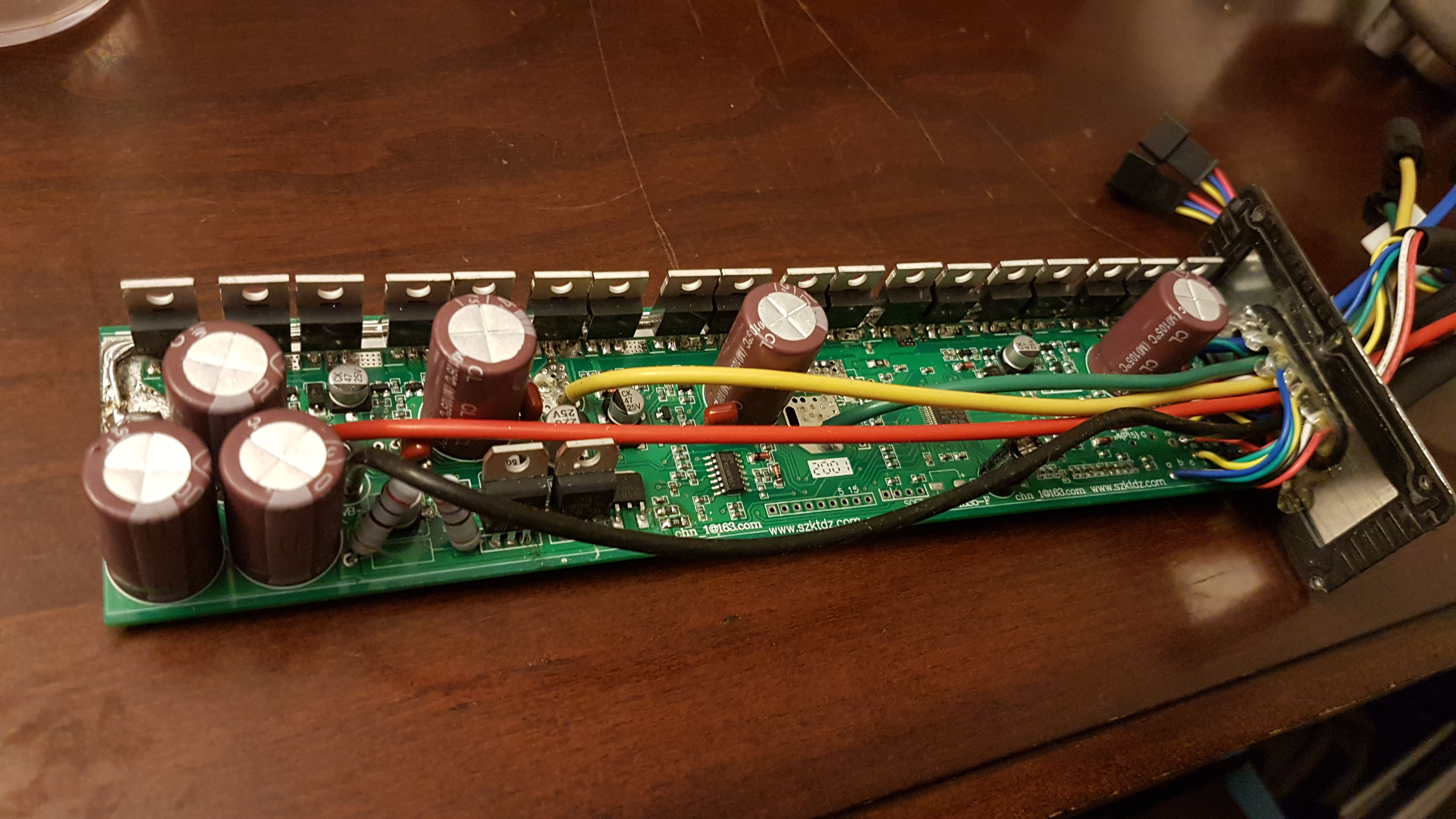
The capacitor in this picture looks burned, it looked that way when I opened it up.

This is a Square Wave Controller I'm told.

Any other advice here for power modifications? I'm sure there are plenty of threads here about this, but I typed in a few obvious keywords about this controller which I know is pretty common and didn't see anything pop up.

Thank you in advance!
 
I don't see any images--if you have them on an external site, they're not visible to me here for whatever reason.

I'd recommend attaching them directly to your post using the Attachments tab--there's no practical limit to the size of the images; it should take just about anything you've got.

Regarding increasing current, I wouldn't expect doubling the current. Even if you change the FETs out for better ones, you can't expect to get the full rated current from any FET, and the more you have the worse the loadsharing is, making it more likely to blow one FET that then puts more load on others that then blows them all like lights in a string. :/

To get some idea what you can do, you might want to look up all the old hotrodding threads by Methods, etc., as they show quite a lot of experiments along this line. Most of that was between 5 and 10 years ago, when high power ebike controllers basically didn't exist, or cost so much that it was simply impossible...nowadays it's not that bad, and they're pretty common (though often of dubious quality).

But the resulting controller can be unpredictable in behavior; I have had a couple of the old experimental units like that which sometiems worked fine, and other times wouldnt' evne drive a motor, for no explicable reason. Eventually both fried, blowing FETs in a phase and taking out the gate drivers, too, even though they weren't being used anywhere near their new capabilies (one not even near it's original!). :(

Sometimes the hotrodding works perfectly...sometimes it doesn't.


Keep in mind that if you do anything to change the shunt, especially by putting solder on it (vs just adding more shunt wires in parallel, or replacing with lower resistance shunts) the controller no longer has any idea what the current actually is, and it cannot protect itself or any of it's components against overcurrent situations, and is more likely to blow up.

Soldering across/over a shunt is also not undoable--once it's done, the resistance is now changed even after you remove it because you can't really remove all of what was added.

And sometimes you don't get the behavior you expect. I paralleled one extra shunt with the existing ones on a "33A" controler, expecting to get something like 40-50A out of it...and I get short bursts of almost 80A out of it for a few seconds, before it limits itself some other way down to about what I expected. I don't know what causes the secondary limiting; there aren't any other current sensors, so perhaps it's got a thermal sensor I don't see, or senses a voltage drop across a FET, etc., to "guess" that something is going badly wrong, and cuts power by half. It's not a very good quality controller, so if it didn't do that it'd probably be a nifty fireworks display after a few more seconds of that 80A. :lol:

But either way--it shouldn't do the 80A at all, as the shunt added shouldn't have changed the total shunt resistance by that much. (but I didn't have a way of measuring to know for sure).

The point of all that is just to say that you may not get what you expect. ;)
 
amberwolf said:
I don't see any images--if you have them on an external site, they're not visible to me here for whatever reason
Show up fine here, I believe you determined it was a fault in the ISP of your neighbor or something?

gomyles said:


amberwolf said:
I don't see any images--if you have them on an external site, they're not visible to me here for whatever reason.

I'd recommend attaching them directly to your post using the Attachments tab--there's no practical limit to the size of the images; it should take just about anything you've got.

Regarding increasing current, I wouldn't expect doubling the current. Even if you change the FETs out for better ones, you can't expect to get the full rated current from any FET, and the more you have the worse the loadsharing is, making it more likely to blow one FET that then puts more load on others that then blows them all like lights in a string. :/

To get some idea what you can do, you might want to look up all the old hotrodding threads by Methods, etc., as they show quite a lot of experiments along this line. Most of that was between 5 and 10 years ago, when high power ebike controllers basically didn't exist, or cost so much that it was simply impossible...nowadays it's not that bad, and they're pretty common (though often of dubious quality).

But the resulting controller can be unpredictable in behavior; I have had a couple of the old experimental units like that which sometiems worked fine, and other times wouldnt' evne drive a motor, for no explicable reason. Eventually both fried, blowing FETs in a phase and taking out the gate drivers, too, even though they weren't being used anywhere near their new capabilies (one not even near it's original!). :(

Sometimes the hotrodding works perfectly...sometimes it doesn't.


Keep in mind that if you do anything to change the shunt, especially by putting solder on it (vs just adding more shunt wires in parallel, or replacing with lower resistance shunts) the controller no longer has any idea what the current actually is, and it cannot protect itself or any of it's components against overcurrent situations, and is more likely to blow up.

Soldering across/over a shunt is also not undoable--once it's done, the resistance is now changed even after you remove it because you can't really remove all of what was added.

And sometimes you don't get the behavior you expect. I paralleled one extra shunt with the existing ones on a "33A" controler, expecting to get something like 40-50A out of it...and I get short bursts of almost 80A out of it for a few seconds, before it limits itself some other way down to about what I expected. I don't know what causes the secondary limiting; there aren't any other current sensors, so perhaps it's got a thermal sensor I don't see, or senses a voltage drop across a FET, etc., to "guess" that something is going badly wrong, and cuts power by half. It's not a very good quality controller, so if it didn't do that it'd probably be a nifty fireworks display after a few more seconds of that 80A. :lol:

But either way--it shouldn't do the 80A at all, as the shunt added shouldn't have changed the total shunt resistance by that much. (but I didn't have a way of measuring to know for sure).

The point of all that is just to say that you may not get what you expect. ;)

Added links below the pictures;
Thank you very much for the detailed response!

Maybe shooting for 120A is a bit of a stretch .. but I feel that this controller can certainly do more than the 60 its rated at (just due to its size, and # of fets )

Wondering if anyone has experience with these, because I know that there was a whole thread about the KT controllers, and modifying their firmware, so I feel there a well understood controller at this point
 
This is a square wave controller. There's only one shunt so it's not capable of FOC or sinusoidal control.

This means it is more likely to behave when you decrease the shunt resistance.

However, it looks like a huge lump of metal and nonsense for not much power. You might consider just buying a new one that is rated for massive current, is half the size and can run sinusoidal control...
 
mxlemming said:
This is a square wave controller. There's only one shunt so it's not capable of FOC or sinusoidal control.
Per-phase current sensing is not required for sinusoidal control (though it is for FOC). ;)
 
amberwolf said:
Per-phase current sensing is not required for sinusoidal control (though it is for FOC)

Q posted in "True FOC" thread
https://endless-sphere.com/forums/viewtopic.php?f=30&t=105139&p=1610716#p1610716
 
amberwolf said:
mxlemming said:
This is a square wave controller. There's only one shunt so it's not capable of FOC or sinusoidal control.
Per-phase current sensing is not required for sinusoidal control (though it is for FOC). ;)

Technically possible for both, but no one does it with good results...

That I'm aware of anyway. Does the casainho code do sinusoidal on single shunt? Is it good as compared to vesc, nucular (st) etc?
 
mxlemming said:
Does the casainho code do sinusoidal on single shunt?

Sinusoidal commutation by a lookuptable yes, but no FOC. In the Kunteng project we have a current sensor on one phase rail. With this we adjust the advance angle by looking at the zero crossing of the phase current.
In the TSDZ2 project he just uses the motormodel for calculating the advance angle from i * omega. For the TSDZ2 it's easy, as there is just one motor, that has to work with the empirical constants.

Both solutions are no "real" FOC with Park --> Clark and back....

regards
stancecoke
 
You mean single shunt on just one leg of the 3 phase bridge? Not bus current measurement? That's not a setup I'd ever thought of using, doesn't this mean any short/erroneous behavior on the unmeasured phases results in instant death of FETs rather than software/interlock catching it?

What about imbalance in the phases? Not that standard FOC does anything about that either...

What's the performance like? Before I wrote my foc algorithm I had planned to just do a sin table lookup, much easier and possibly more robust.
 
mxlemming said:
just one leg of the 3 phase bridge? Not bus current measurement

No, one shunt on the GND rail, plus one ACS712 on one phase.

In the 6 step version of the controller, the ACS712 is missing.

regards
stancecoke
 
Back
Top