Hi all,
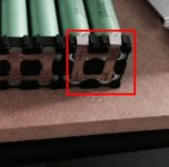
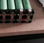
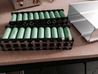
I am building a 10s4p pack of samsung 25R cells for my BBS02 36v 25A peak 750W motor. The pack will be made of two 4p5s packs as shown in the picture below. I have connected the cells within the two subpacks, I am using some nickel strips 7mm x 0,15mm. I am still waiting on a 10S BMS from elifebike to go on.
I have two questions about the next steps so I am looking for some advice:
- my nickel strips are rated for 20A constant current but my BBS02 may peak at 25A. I know the 20A is a conservative rating but I don't know how "conservative" that is. Do you think I am safe with these nickel strips ? If not, changing the strips is not an option, they are the only ones avaialble for the kind of cell brackets I am using. So, if needed, would it be ok to just add a "second layer" of nickel strips over the ones I already welded to double the cross-section area of my strips? Last option for me would be to downgrade the BBS02 controller to 20A which should be enough for the way I plan to use it.
- I hesitate between two different builds to connect the two 4p5s packs together:
Option A: I build one big "whole" pack: connect a 10S JST-XH balancing wire to the two subpacks, tape the BMS, tape the two packs together and put the big package into some shrink tube
Option B: I build it as two separate 4p5s subpacks with their own 5S JST-XH balancing wire, their XT60 +/- connectors and their own "shrink tube" protection. Then I add a XT60 series connection, a 2x5S to 10S JST-XH adapter (if that exists??) and tape the BMS on top of the two subpacks.
Do you guys have any idea on the best way to go?
Anyway, I am all ears if you have any other general advice about going on with this build!
Thanks a lot!
Csheep
")