Another attempt at building a motor controller

I finally got around to replacing the gate resistors.
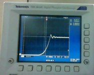
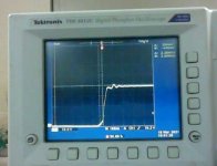
@mxlemming you were correct about the gate resistors being too low, switched 4.8r to 8.2r and there was only 4v of ringing at 20v, 6v at 40v. Ringing is still almost completely independent of phase current at above 20 amps. Total switching times (Id increase and Vds decrease) are around 150 nanoseconds, which is a bit longer than ideal but the FETs still run pretty cool.
High- and Low-side gate drive waveforms are nearly identical.
View attachment 1

There is a bit of bouncing (~2 volts) when the gate drive to the FETs crosses the threshold voltage, but it only increases slightly with voltage and very slightly with phase current.

I can't do any high-power motor tests because Vector sent me the wrong motor and I can't clamp it in my frame. When the correct motor arrives (1-2 weeks), I'll put the scope on it again and see how it switches at higher voltages and currents.

If all goes well with that test, the next version of this controller (using 36 TO-220 FETs) will go off to JLCPCB to get produced. Fingers crossed that the next controller can switch faster.
 

Attachments

  • webcam-toy-photo8.jpg
    webcam-toy-photo8.jpg
    40.3 KB · Views: 1,359
  • webcam-toy-photo7.jpg
    webcam-toy-photo7.jpg
    39.4 KB · Views: 1,359
3 weeks later and I finally had enough of a break from other projects and classes to work on the controller again. Accurate angle tracking was a pain with the trapezoidal. The BEMF looks something like this
BEMF.png
and passing the waveform through the DQZ (Park + Clarke) transformation yielded an angle measurement that had quite a few bumps in it, due to the non-sinusoidal BEMF.
AngleMeas.png
Getting that smoothed out was challenging, as I had to build a PLL. For the sake of learning, I decided to write it from scratch, using a PID-style control to control the virtual speed. Dealing with radians being a circular number system was the hardest part, the constrain() function was much more complicated than the C++ one-liner, with 4 different cases.
After debugging (took over an hour), the PLL completely eliminated the ripples in the position measurement at all but the lowest speeds. Which doesn't matter because I'll be doing saliency at those speeds anyway :)
Code for the PLL: View attachment FOCSnippet.cpp (Not sure if terminology is correct but it works)

Even though the position detection was buttery smooth, the phase currents were all over the place due to the extremely non-sinusoidal BEMF of the motor. The PID control I'm using is too slow to respond to changes in current. If I try to stiffen it, the system oscillates and the motor emits a terrible whine.

The future motor control algorithm will model the motor as a (roughly) known inductance with an unknown voltage on the other end. With each iteration, it will adjust the output voltage so that the error gets halved on each PWM cycle. This algorithm will also yield a good real-time estimation of each phase's inductance at higher speeds, so I will have two separate sources of rotor position. Won't be too hard to design, either, as voltage is the only unknown.
 
I've been having a really hard time over the past few days trying to get the stupid PID loops to track the current without lagging behind at higher speeds. Turns out what I was initially doing wasn't FOC at all :oops: The PID loops were attempting to regulate the current of each phase instead of the D and Q currents directly, and they started to seriously suffer past a few thousand ERPM.

With the PID controllers in the right place, torque delivery is smooth, efficient, and powerful, even up to the highest ERPMs. Once I get sensorless from standstill working (approx. 2 weeks), this will truly be a next-generation controller.
...
In terms of performance, this controller is super overkill for the "1000 watt" hub I'm currently running it with. After a 3-mile, 15- minute (slight uphill, some off-road, no throttle discipline) ride to a friend's house, the FETs were a few degrees above ambient... but the hub was smoking a little :eek: . Good thing the wiring was undamaged and it was just the acrylic I sprayed on to waterproof it. I was running 120 phase amps for that run. No heatsinking on the FETs whatsoever except for the aluminum bar.
...

The code is up at https://github.com/thorlancaster/ThunderFOC. Very simple FOC implementation, no trade secrets yet.

Commercialization
The board I posted about 3 weeks ago should arrive in a few days. Given how well this board is doing, I have little doubt that the new board will be able to push 450 phase amps continuously without issue and at least 600 peak, with all the modern goodies (field weakening, regen) plus a bit more (super-fast hardware protection, sensorless from standstill, phase resistance / temperature monitoring, ABS regen, traction control, and an open Serial interface for easy integration with Arduino). The hardware will likely be open-source and designed for repairability.

AND... It will be made in the USA using a minimum of overseas parts (Mexico FETs, America enclosure / heatsink, Aisler(USA) board)

Price will probably start at $420 + shipping. I will most likely make a kit available as well for around $180-300 depending on what is already soldered. I'm getting a pick/place with my stimulus money so I should be able to meet demand unless there is a huge amount.
 
Looking good. The current state of controllers are:
Sabvoton: works, regarded to be mediocre.
VESC: kind of works, very variable quality, no field weakening MTPA etc... Likes to explode itself
Nucular: seems to be regarded as the best, crazy lead time.
ASI BAC: seems hard to buy... Many $$$
Kelly: like to go bang bang, mediocre commutation
Peters controller, MESC, other forum customs etc: not available to buy.

Others seem to not really be any good or not available, or not applicable to higher volts/powers.

There's space in the market for something that comes out of the box and works with minimal setup and fettling. I learnt this the other day when I fitted a Chinese ebike kit in 3 hours, compared to the ~300 hours I've spent on MESC, coding, PCB design and debug, cutting metal and designing belt drives etc on my ebike.
 
That's a great project I'm impressed on how fast you did it. A version with all the SMD soldered is good idea for DIYers.

Be careful on component selection and availability, for example the current sensor has a 6 months lead time.
 
It looks fast if you discount the 2 previous failed attempts https://endless-sphere.com/forums/viewtopic.php?f=30&t=94443 - :? before I knew what I was doing. This was not my first high-power project either, I've been working on class D amplifiers for a few years.

Thanks for pointing out the stocking issues, never thought of that. The current sensors aren't that big of an issue. I can alter the thickness of wires used as current dividers so I can run anywhere from the 50 amp all the way down to 17 amp ones.
But you have a good point, given that non-ratiometric is in short supply. If I set up an ADC pin to measure the 5v rail, non-ratiometric sensors will be perfectly usable.

Other than those, all of the parts either have hundreds/thousands in stock (SMPS / logic ICs / FETs), or can easily be replaced with an equivalent (passives). I think I'm good to go with existing BOM, at least for the first 10 boards.
 
mxlemming said:
There's space in the market for something that comes out of the box and works with minimal setup and fettling. I learnt this the other day when I fitted a Chinese ebike kit in 3 hours, compared to the ~300 hours I've spent on MESC, coding, PCB design and debug, cutting metal and designing belt drives etc on my ebike.

:thumb:
This is very true. I've spent a similar amount of time on this project myself, at least 80 hours so far if you only count this controller and not the battery / frame / etc. Probably around 150 by the time I have something working and ready to sell. If I counted labor as a cost I would already be way over any commercial controller... I call labor free though, I'm learning a ton about advanced power electronics.

Getting this to work out-of-the-box with almost all motors shouldn't be too hard. When the controller starts up it will measure phase inductance and set the PID gains accordingly. The PID loops will also be self-adjusting; Gain will increase if the loops are struggling to track BEMF and will decrease if ringing is detected. To help drive motors with non-sinusoidal BEMF, I might use a lookup table to track BEMF vs angle and take the work of tracking the varying D/Q voltages off the PID.
These are just ideas, some of these might not be needed at all.
 
That 36-fet board I mentioned earlier arrived and I finally had time to work on it. To start with, I only put in one half-bridge (out of 6) to minimize the amount of components I had to desolder/resolder to experiment with parameters.

Without a load, the waveform was beautiful. Fast, clean transition from 0 volts to battery voltage in ~50 nanoseconds, no overshoot and very little ringing.NoLoadSwitch.jpg.

As soon as I added current, things got nasty quickly. At 40 volts and 20 amps I was getting spikes on the switching node that exceeded twice the battery voltage :( . Increasing the gate resistors to speed up switching didn't help either, as soon as the FETs hit their Miller plateau everything started to oscillate. After reading this https://toshiba.semicon-storage.com/info/docget.jsp?did=59456 paper, I realized that my circuit had turned into a Hartley oscillator.

Voltage between switch-node and Battery-
20AmpSwitch.jpg
High side Vgs
20AmpGate.jpg

Placing a 47nf capacitor directly across each FET's gate-source terminals cut down on the gate ringing, but the switch node was ringing almost as bad as before. I don't have photos but the overshoot voltage was now around 8 volts over Vcc if I remember correctly. Although it wasn't nearly as bad as before, the ringing was still intolerably bad for the currents I wished to run. In addition, some of the FETs were running significantly hotter than others.

The solution...
...
...
... Ended up being something that another member (Marcos IIRC) ended up having to do with his controller as well. Placing two 0.9 ohm / 2.2nf snubbers across between the switch node and a power rail reduced the ringing to almost nothing, even at higher currents. The problem with my initial design is that when the FETs switched on fully, they caused an oscillation between the leg inductances and the output capacitances of the FETs, in the neighborhood of 55 MHz. I wasn't expecting the frequency to be anywhere near this high, probably because the inductance was so low.
80AmpsSwitchSnubber.jpg
This is beautiful. 80 amps at 30 (skimpy wiring can't hold voltage) volts, very little ringing, no overshoot whatsoever. This is very clean and certainly cleaner than my older controller. The FETs are now running significantly cooler than before and most importantly they are all the same temperature.
There's still a hint of ringing as the FETs switch, but it's absorbed by the snubber by the end of the transition and never overshoots at all. 250 amps (max peak current) should be a bit noisier, but still plenty clean enough for the final product. I will most likely test that tomorrow.

The board so far:
Board.jpg
 
I know what you're thinking: "Isn't all this capacitance going to cause tons of switching losses?"

I was thinking the same thing, but it isn't that bad.
Putting 12v into 56nf requires 0.000004032 joules. If I am switching all the FETs at 20 KHz, this results in a power dissipation of 2.9 watts across 6 gate drive circuits. The 0.48 watts dissipated by each driver stage is enough to make them warm but not hot. Finger thermometer estimates a rise of around 10-15c in the gate drive circuit.

If I do ARSVPWM (SVPWM but instead of a triangle wave I clamp the closest phase to either Vcc or GND), the switching losses will be cut by a third. I'd take 2 watts of gate drive power any day for a controller of this size.

The snubber power loss isn't bad either. 85v, 2.2nf, and they dissipate energy on rising and falling transitions. 0.3179 watts apiece, and there will be 12 of them. That's 3.8 watts normal, 2.56 watts with ARSVPWM. Not a problem at all for a controller that should be able to do 20+ Kw peaks.
 
What FET did you use in the end?

Could you build up the other 3 phases with different FETs?

I recall debating with you whether the high Miller cap FETs were a good choice. Here's a great opportunity to try with various options.

When I built my first d2pak controller I used Infineon on one leg, TI on another and on semi on the third. The difference in switching with everything else equal was stark. None were especially better than the others but the Infineon was noticably slower with less funniness (higher Cgs) and the TI ones had strange oscillating artifacts on the legs.

Still rode it around with a mish mash of FETs without issue.

Peter's controller thread had a lot of snubbers and their effect. Maybe that's what you're thinking of?

I wasn't thinking atall about the gate driver power losses... In the case of adding capacitance, the losses directly to the caps are insignificant compared to the losses to switching hundreds of amps slower.
 
mxlemming said:
What FET did you use in the end?

Could you build up the other 3 phases with different FETs?
I ended up using the IRFB4110. It is widely available, generally regarded as a good MOSFET, and only costs $2 a pop in quantity. There are better fets (like IPP023N10N5) with less Miller and better RdsON, but they cost over 2x as much.

Never really thought about using different FETs in the other two phases. After I sell a few I might build a test controller with different FETs in each phase to decide whether pricier FETs are worth it or not. Will probably stick with 4110s though.

mxlemming said:
I recall debating with you whether the high Miller cap FETs were a good choice. Here's a great opportunity to try with various options.
I tried several different ways to tame the miller capacitance. Results from worst to best:
- No anti-Miller capacitor at all (horrible)
- 10nf on the PCB about 1cm away
- 47nf on the PCB about 1cm away
- 10nf soldered directly between gate and source
- 47nf soldered directly between gate and source

When trying to tame oscillations in the neighborhood of 50MHz, the capacitor must be as close as possible to the FET legs or it won't do much because of inductance. Bodging the caps in between the gate and source terminals worked surprisingly well.
GateCap.jpg.
My conclusion is that anti-Miller caps are a godsend for circuit stability with Miller-y FETs, even though they increase gate driver losses and need to be placed carefully.

mxlemming said:
I wasn't thinking atall about the gate driver power losses... In the case of adding capacitance, the losses directly to the caps are insignificant compared to the losses to switching hundreds of amps slower.
I 100% agree when it comes to driving a motor, but I also want this controller to be able to do efficient MPPT off of a solar panel / array. One phase switching at 20 KHz with 12v gate drive and 80v battery uses about 2.3 watts idle, which is tolerable but I wish it was lower.
 
So...
I won't be continuing with the 36-FET board. There are still some small issues with even heating and I don't want to have to solder 36 FETs for a production controller. I decided to put this controller to the side and add snubbers to my 12-FET IRF100P218 controller...

Before snubbers @ 20v 20a:
osc1.jpg

After snubbers (2.2nf with 3.0r x2 each phase)
osc2.jpg

And the results were nothing short of amazing. The ringing amplitude (which was already borderline acceptable) was cut by a good 30-40%, even while switching faster than the 4110s. Even though the 4110 controller was looking good at 80 amps, it gets messier the higher I go. Even if the FETs do avalanche a bit, the IRF100P218 is rated for OVER A JOULE of avalanche and a very liberal estimate (100v 50a 40ns triangular) is only 0.1 millijoules. This estimate is probably way too high and preliminary testing (a few pages ago) suggests I won't even hit avalanche anyway even when driving 450 amps into my QS205.

Next prototype (hopefully sellable :wink:) will have 6 IRF100P218 FETs on each side with roughly the same layout. Sort of like Peters's controller. If that controller performs as well as this one, I should have something the size of a common Chinese 12-FET that does 400+ phase amps.
 
This is still quite a lot of ringing, and your current is quite low.

https://endless-sphere.com/forums/viewtopic.php?f=30&t=107672&start=100 my one at 187A

https://endless-sphere.com/forums/viewtopic.php?f=30&t=110674&sid=e5675e333a36693c0e981307653a5bc3&start=25 Peters' one at 210A

It might work, but I really don't think you need to accept this much ringing. More snubber tuning perhaps.

Avalanche in small quantities will only be ok as long as it's able to dissipate the heat. Which it probably can... 0.1mJat 20khz is 2W. Probably fine...
 
A while back,
mxlemming said:
Could you not have just made your PCB 5mm bigger and put the caps on properly?

I really should have. A few days ago, I was cruising along at ~25 MPH, not accelerating much, and then a long, soft popping sound and the controller lost all power.
Having a solid strip of caps epoxied to the board was great for decoupling, but not for safety. Having all of the caps touching and glued together was a recipe for thermal runaway. Once one capacitor popped and got white hot, it melted the capacitors next to it, causing them to short, and the whole row went :flame: :flame: :flame: in an instant. It only stopped when the wire connecting the negative rail to the pack blew like a fuse.
Capacitors_go_blowie-blowie.png
After reading some documents on MLCC failure, the way I soldered them to the board was also a big no-no. Soldering them straight to the bus bars put a good deal of thermal and mechanical strain on them, and as soon as one failed, the above happened.

The good news is that after I replaced the blown caps (leaving a little space this time), the controller is now running again.
 
Although this version works well (aside from the Captastrophe), it was a total PITA to assemble and debug. Since I plan on commercializing this, I have made some big changes to the next version.
* More ceramic capacitors, placed properly. No more thermal shock when soldering and if 1 blows, it's not the end of the world.
* More electrolytic capacitors as well. The ones on my board got pretty hot (200 peak phase, ~100 continuous, FETs can easily do 250 continuous)
* Brain, Gate Drivers, and FETs on separate boards. Makes debugging (and future warranty repairs) a whole lot easier, not to mention the much smaller board footprint.
* Hardware Overvoltage/Overcurrent protection. Bus goes over 90 volts, FETs turned off in hardware. Bus goes over 95, DC-DC converter disconnected. Phase or battery current will also turn off FETs until uC turns the enable line off and on again (like a circuit breaker).
* Lower resistance power stage - power is fed in at the center of the power stage (vs. the ends) and phases are centered between the FETs. Should cut powerstage resistance in half.
* Brain board now supports 2 throttles (one for acceleration, one for regen)

Brain.png
Brain board contains Teensy and sensorless hardware.

DriverBoard.png
Driver board contains gate drivers, electrolytic cap bank, and protection circuitry. Each capacitor is 220uf / 100v / 80mOhm. Capacitors will be horizontal in finished product.

PowerBoard.png
Power board contains FETs and a ton (152) of ceramic capacitors (some on the back). These are important to prevent bus voltage excursions at high phase currents and make life easier on both the FETs and electrolytics. The bus bars traces are also 3x wider than the previous design (considering both sides) and lower power stage inductance is never a bad thing. Feeding the power in at the center and splitting the power stage in half will cut the current in the power stage in half and resultant heating in the buses by a factor of 4. Cool power stage = cool legs = happy FETs.

...

The boards should arrive in a week. I have a friend who has metalworking tools and have ordered a Creality Ender 3 pro 3d printer, so this will be a professional, sellable controller if everything goes according to plan. I figure I can make 1 a day if I get JLCPCB to do the cheap, numerous SMD passives.
The brain board has a serial port as well. Next project will be a CycleAnalyst-style display controller with an IMU. Since it has both an accelerometer and a gyro, I should be able to do traction control and stable wheelies.
On my current design, a few FETs failed due to arcing to the insulator and one phase is running with only 2. After 200 amps / 5 seconds that phase's FETs are still pretty cool, definitely cool enough to comfortably hold a finger on continuously. With only 1.08 mOhm and 2x the bond wires of most TO-247 the IRF100P218 was definitely a good choice for this project. </rant>
 
Thanks for posting the failure pics, many would like to sweep that under the carpet!

Tbh, I was kind of anticipating this. Glad it happened before you went to production! Really interesting to see it actually happen in the wild.

How big is this? Looking like quite a pile of stuff.

Look to your code for why the capacitors get so hot. Note:
I run 2x470uF, not special, caps. Really don't get hot at 80A.
The 24fet nucular I think only runs 4 caps, good to 400+ amps.

You shouldn't need half as many caps as folklore has us believe if your algorithms are good.

Centre aligned pwm at 20khz gives 40khz switching, run the math based on that and consider the wires to the battery have only a few uH inductance, and the modulation means the switching per cycle happens in a few stages.

Good work!
 
thorlancaster328 said:
Since it has both an accelerometer and a gyro, I should be able to do traction control and stable wheelies.

Being a vehicle dynamics guy, I believe this is the killer app that will separate current- from next-generation controllers (or, as you may prefer, technically next-generation from functionally next-generation).

It is interesting that how this problem is addressed depends on one's background and product. Controller-only manufacturers like Adaptto popularized overspin detection as traction control (though PV also has overspin), and ASI/Grin and Nucular both allow acceleration limits. But being open-loop, these are not true traction control.

But rather than open-loop drive or deriving from accelerometer, true traction control (as implemented by OEMs) requires capturing front wheel speed (allowing for size correction) and limiting slip ratio to <10%. Fortunately, wired bicycle wheel speed sensors are cheap and ubiquitous.

Likewise, wheelie control has been done, and while fun (like wheelspin), wheelies are not only loss-of-control safety hazards, but they also restrict torque delivery and thus acceleration (proportionally to wheelie angle). Therefore, on any commercial product (but especially for performance/racing), I'd refer to see wheelie avoidance, rather than control. And again similar to advanced race/OEM active suspension, the real way to do this is by capturing suspension data, even if just by dumb binary switch on the front fork. Since an ebrake switch only allows throttle cut (this is a baseline feature for me), a separate controller input (even just open/closed) could allow closed-loop power modulation: wheel loses contact = fork tops out = switch closes, so cut power 10% every 0.1s until switch reopens = wheel regains contact. Similar to flat-shifting ECU (holding full throttle w/ fuel/spark cut during shifts), this would allow safely holding (full) throttle to maximize acceleration. Fortunately again, such switches are cheap and ubiquitous.

I would strongly request/encourage an extensible (via inputs) systems-level approach to traction control and wheelie avoidance, rather than investing time/money in packaging and deriving everything (accelerometer and gyro).
 
mxlemming said:
How big is this? Looking like quite a pile of stuff.
The board is 160x86mm. I designed it to fit onto this heatsink - https://www.heatsinkusa.com/3-500-wide-extruded-aluminum-heatsink/. With 3 layers of pin headers, the finished controller should be 3.5" wide, 7" long, and a little less than 3" high including the cooling fins.
There won't be much air inside the controller, most of the empty space will be filled with (probably an excessive amount of) electrolytic capacitors. It'll be a pretty heavy hunk of parts but it'll definitely be reliable. Pretty cheap too, I managed to score some IRF100P218 for only ~$4.40 a few days ago on octopart, let's go check Octopart to see what the stoc...

:oops: :oops: :oops:

IRF100P218 is now out of stock everywhere and the soonest anyone is expected to get any stock is September. Looks like I'll need a different FET. Although not as good from the IRF100P218, the IRF100P219 looks like an okay replacement. Looking at the datasheet, it seems that the '218 is just 2 of the same die in the '219 but due to bond wire limitations the max currents are pretty close. Calculated max phase amps for a 12-FET x IRF100p219 (provided the motor is spinning and each FET can take 180A for a few seconds) is (180 * 2) * sqrt(2) = a little over 500 phase amps. Will derate of course but 400-450 is still enough for a QS205 3t IMO. When the '219s arrive I plan on building a "sacrificial" controller, fusing the battery to ~100 amps, and seeing how many phase amps I can push before the fets go :flame:
On the bright side, I have 38 of them "in stock" in my personal FET stash - enough for mine, one to sell, and spares. 8)

@mxlemming Good insight, never though about that. Regarding your comments on voltage ripple, I'll try different PWM styles and see what causes the least voltage ripple once my new board arrives and is populated. I'm already doing center-aligned though. Perhaps Nucular either has really high quality caps, are pushing them really really hard, or both. Time will tell on this one...
 
fatty said:
thorlancaster328 said:
Since it has both an accelerometer and a gyro, I should be able to do traction control and stable wheelies.

Being a vehicle dynamics guy, I believe this is the killer app that will separate current- from next-generation controllers (or, as you may prefer, technically next-generation from functionally next-generation).

I would strongly request/encourage an extensible (via inputs) systems-level approach to traction control and wheelie avoidance, rather than investing time/money in packaging and deriving everything (accelerometer and gyro).

I agree that this is the best way, and it's what I am pretty much planning on doing. The controller will have a UART running out to a secondary board with IMU, display, etc. The protocol will be simple and open-source (unlike the main firmware) and will probably consist of [Address] [Value] [CRC16] ['\n']. At 9600 baud, sending 100+ of these packets per second will be doable. The most-used address will be the one for the commanded torque, but other values will also be resent periodically to ensure reliability in case a packet occasionally gets dropped. If you've ever analyzed the Daktronics scoreboard serial protocol it will be pretty similar.

For safety, if there is no control packet within ~100ms (register configurable), the torque will go to zero to avoid possible bike flippage.

Once I get the main controller working, I will get the IMU and display unit made next. The beauty of this system is that you can run it either as a stand-alone controller with just throttles, or use the same serial port as for programming to connect to an external control board.
 
fatty said:
And again similar to advanced race/OEM active suspension, the real way to do this is by capturing suspension data, even if just by dumb binary switch on the front fork. Since an ebrake switch only allows throttle cut (this is a baseline feature for me), a separate controller input (even just open/closed) could allow closed-loop power modulation: wheel loses contact = fork tops out = switch closes, so cut power 10% every 0.1s until switch reopens = wheel regains contact. Similar to flat-shifting ECU (holding full throttle w/ fuel/spark cut during shifts), this would allow safely holding (full) throttle to maximize acceleration. Fortunately again, such switches are cheap and ubiquitous.

I never thought of this approach but it makes sense if one is actually trying to avoid wheelies. With the gyro approach, you can't detect a wheelie happening until the front wheel has risen off the ground. I would personally prefer a linear suspension excursion sensor. Easy to make with a hall sensor, an appropriate magnet, and a few 3-d printed parts. Although a binary switch could also work here, it would be nice to adjust the front wheel pressure to suit the terrain etc.

This stuff is still a few months down the road but it's fun to think about.
 
Stumbled on this thread looking at different MOSFETs with low RDS values. Seems as if although the IRF100P218XKMA1 is now obsolete, it is being replaced with the IRF100P218AKMA1 from January next year. Not sure what the difference is but it might be of interest to you. Also, have you thought about some of the surface mount MOSFETs from Infineon like the IPT015N10N5?

Brilliant work BTW :)
 
uPET said:
Stumbled on this thread looking at different MOSFETs with low RDS values. Seems as if although the IRF100P218XKMA1 is now obsolete, it is being replaced with the IRF100P218AKMA1 from January next year. Not sure what the difference is but it might be of interest to you. Also, have you thought about some of the surface mount MOSFETs from Infineon like the IPT015N10N5?

Brilliant work BTW

I did end up ordering a few tubes of 'KXMA1 FETs and they work even better than the originals. Currently this controller is on my daily driver Vector eBike and does 260 peak phase amps with no heatsink other than aluminum bars bolted to the FETs. Continuous is of course much lower, I mostly ride it around town at sub-30 MPH. I did try going to 320 phase and the bike was somewhat wheelie prone. My current controller has done around 500 miles at 260 peak, mostly much lower.

Also, have you thought about some of the surface mount MOSFETs from Infineon like the IPT015N10N5?
I have and am currently developing a controller with them. The massive source and drain terminals are a plus too, they really cut down on the bond wire inductance/resistance and I should be able to carry the same peak amps with a controller half the size.
 
Back
Top