Arduino Nano Cycle Analyst (and other) companion TidBits

LewTwo said:
While you are considering design features, consider a optional button for throttle 'cruise control' :)
The CA already has a feature where you can set a specific time to monitor you holding the throttle in the same position, and then start cruise then you let go of throttle. Not a useful feature for city traffic that I'm in, so i don't use it, but it's already there, so if you're using the torque-startup-from-stop TidBit to make a CA do that function, then you're already using a CA that has this feature. ;)

Anyone is welcome to toss in code to make this possible in any of the TidBits that output a throttle signal (there shouldnt' be any other hardware needed beyond a button input on a digital input, and debounce hardware or code). I don't think I'll be writing a fucntion that does that myself, though.

If you really want that feature without a CA and the controller doesn't have it, then sometimes one can find the old Crystalyte Cruise Control modules, which not only have CC but +/- buttons to increase or decrease the cruise speed:
It just goes between the throttle and the controller, and basically "samples and holds" the throttle voltage present on the input when engaged, then can inc/dec it via the buttons. I think it uses the ebrake to cancel (can't remember if it also works via button or throttle movement). There's a bunch of threads about it over the years (most pretty old). I have one around here somewhere you can have if I ever find it.
https://www.google.com/search?q=Crystalyte+Cruise+Control+modules:+site:endless-sphere.com&newwindow=1&hl=en
https://www.google.com/search?q=Crystalyte+Cruise+Control+modules:&newwindow=1&tbm=isch
It's still listed on their pages
http://www.crystalyte.com/Crystalyte%20motor%20related%20part.htm
but I cant' find a link to buy anything there. This site
http://www.electric-bikes.com/betterbikes/throttles.html
has it for $30.


Regards to powering the Nano:
It sounds as if the Nano's on board 5 volt regulator (5-12 volt DC input) would provide sufficient power.
If that be the case considering separating it into to projects: one for the nano and one for the power supply
The Nano's supply is plenty for the Nano itself and probably for the other stuff to be used with it.

However, the Nano requires conversion from the battery voltage (or lighting power voltage) both of which are higher than it can take as input, so that's why I'm trying to wokr out the LVPS for it.

There *will* be a pcb option for the I/O, etc., parts to go onto the headers, and the lVPS would also be on that, if someone chooses to use it. I just want to make an option for the stepdown that is very very simple to use / build and can literlaly just be tacked onto the headers for super-minimalist TidBits. :)

If anyone wants to design a completely separate PCB / module for the LVPS with stuff like the regulator chip Thorlancaster posted, they are definitely welcome to post it here (eventually I'll figure out how to use Github so it can also all go there, but first I have to get past pseudocode so there will be something to put on GH). Even if I can't build it, I'm sure others can, and so they can use it where I can't.


You indicated you already have a secondary voltage source for lighting you could use. Many others are likely in the same boat.
Unless the supply they have is no more than 12.0v then AFAICT it can't be used to power the Nano directly, it has to be stepped down first. Mine is 16.4 fully charged (4s NMC), and anyone else using a battery for "12v" lighting will also be higher than 12v at full charge. (3s "li-ion" would be 12.6v typical, lead-acid would be 13.6v+, etc).


Or they could use one of the previously listed Step-Down sources.
Or they could build the power supply project.
More choices = flexibility :wink:
Yes...but I would like something that can be built into a tiny pcb to mount to the edge headers of the nano, or be directly wired to that edge header.

Others can alwyas choose to use something different, but if a solution is already provided, it might be that more will want to use these TidBits. (I know that if I have to come up with this bit and that bit and this other bit to use something, i'm a lot less likely to get around to doing all that, than I am to just use something already there, or easy to put the parts together for--I'm sure I'm not the only one).


I must sound terribly obstinate, but I suspect that readers might be skipping some of what's posted (I type a lot ;) ), and may be missing some of the reasons. Or maybe I didn't state them clearly enough, or even forgot to state them initially. (too exhausted most of the time, so I cant' remember what's been posted until I re-read it all each time, which is part of what takes me so long to do anything).
 
amberwolf said:
I must sound terribly obstinate, but I suspect that readers might be skipping some of what's posted (I type a lot ;) ), and may be missing some of the reasons. Or maybe I didn't state them clearly enough, or even forgot to state them initially. (too exhausted most of the time, so I cant' remember what's been posted until I re-read it all each time, which is part of what takes me so long to do anything).

No, you're not being obstinate. Your specifications for the functions desired for *this* project are very clearly spelled out in your original posts on this thread, available to all of us to (re)read. We're seeing the natural human tendency of wanting to 'improve' whatever we encounter, which can lead to feature bloat if the original design parameters get lost in the shuffle. If necessary, someone can always 'fork' this particular project and take it in another direction.
 
For sensing speed or distance I am looking at using one of the hal signals from my 9C DD hub. I believe it has 50 or so motor poles so that would come out to about 300 Hz for roughly 50 kph. On the Arduino side that could trigger an interrupt routine that I would have simply increment a counter. Would that work, or should I be looking at the old reed switch and magnet on spokes method? I'd like to avoid extra sensors if I can.
 
For those helping, I haven't abandoned this. :)

Just been tired and trying to read up more on the Arduino stuff, to be sure that what I need to do will work with the circuitry on the Nano itself, with only very minimal parts added to it (that hopefully can mostly, or completely, be "dead bugged" to the Nano's edges, rather than having to make a PCB to hold them, wherever possible.

I haven't had enough brainpower to go back thru the psuedocode again yet to refine it.

Unless someone else has a better thru-hole regulator solution that's tiny and simple to implement, I'm going to order some of these:
https://www.mouser.com/ProductDetail/689-LR12N3-G
(for all the TidBits that are sub-50mA, which I hope is all of them)
and these:
https://www.mouser.com/ProductDetail/595-TL783CKCSE3
(just in case I end up with any of these TidBits that need more than 50mA)

If there are other bits and bobs that Mouser might have for this general thread's projects that any of you know of, I can order them at the same time, to minimize wasted money on shipping itty bitty things.
 
I'm working on my Arduino meter as well. I wired directly to the Promini unit ( similar to the nano, but smaller ). I did use a tiny perf board to hold some small auxiliary stuff like voltage divisor resistors. For now I'm displaying on a 20x2 LCD. I build a separate 'pod' to hold the hal current sensor I ripped from a burnt controller. I'm having an issue with my idea to use the motor hal sensor signal to get speed. The signal works great when I spin the wheel by hand but it reads a bunch of noise if I run the motor. Does anyone have some part numbers for the hal used in most DD hubs ? I want to see how I can approach the noise filtering, like with a capacitor or a pullup or pulldown resistor. It would be so much better if I can avoid an external speed sensor. I tried a 7414 Schmitt buffer on the hal line, but it did not help. The good news is it reads the current and Volts ok. I'm not doing anything with a throttle signal yet, maybe later.
 
Update: Well. I seemed to fix the hal speed sensor noise issue by adding a 0.1 uf cap to ground from the hal signal. But now I seem to have lost my nice hal current sensor . :evil: :evil: :evil: I am not happy about that as I don't have spares laying around. I may take one from a semi-working controller as I simply can't wait for a shipment. So pissed. I had it's output wired directly to the analog input on the micro which may be an issue if for some reason it was fighting with it. Adding a 500 ohm resistor would help this I think.
 
amberwolf said:
If there are other bits and bobs that Mouser might have for this general thread's projects that any of you know of, I can order them at the same time, to minimize wasted money on shipping itty bitty things.
A corollary to Murphy's law: No matter how many 'bits and bobs' one orders the one you eventually desperately need is the one that you did not order. Evidence is my 50 Cal ammo box with 10 pounds of various connectors.
 
That's true. And there will always be more stuff I'll want or need from wherever...but I figure at least for now, I'd get the bits I would need for the specific project ideas in this thread.

Speaking of which, I'll link an idea here based on someone else's:
https://endless-sphere.com/forums/viewtopic.php?f=14&t=110900
It's a very simple UI coulomb counter battery gauge, in the general vein of Jeremy Harris' simple ebike fuel gauge but even simpler and cheaper.

My complication / concatenation / mutilation of their ideas would be something like this:
I might eventually work out a way to use your basic idea (flashing a pair of LEDs to indicate capacity state of battery) except with an LED that changes color rather than flashing (as with my personal capabilities I would have to stop completely to have time to count flashes, but I could get the gist of battery state with a color along the "rainbow", if it "continously shaded" the color from violet down thru blue, green, yellow, orange, to red. Since I don't like bright point sources, but would need something daylight visible, that is also not too bright while riding in traffic at night, I'd probably use three PWM'd outputs to drive the R, G, and B of a larger-surface-area LED (array?), perhaps a half inch on a side with a diffuse surface, and an analog input to read a light sensor (photoresistor in a voltage divider?) to dim the LED as ambient light also dims. If no analog input is available, then the photoresistor could control an offset of the base voltage to a transistor that controls the current thru the common connection of the RGB LED(s).

So I might look up a little fingernail-sized RGB LED unit that would be able to display that, and get that from Mouser at the same time. I don't actually need a battery gauge like this with the CA, but I have sometimes thought about moving the CA off the bars into the wiring / etc compartment, as I don't need any info from it most of the time, except occasionally would like the present battery status. This would do that better than a voltmeter (which I don't want to use).
 
I'm 70% done with my Arduino bike display. Just software and calibration tuning now. Using a two line 16 character LCD. So here are some things to consider in making one of these. Speed sensing: I managed to use the hal signal from the motor on one of my bikes that has a direct drive motor. Things on paper don't work so well in real life and the reason is 'noise' Took me a while to solve that one by putting a small capacitor from the hal to ground. Took three tries to get a value that worked to kill the noise but not effect the top rpm of the motor. An unmarked ceramic cap less than 0.1 uf. So noise is an issue. Like for the current signal. I'm using a hal based current sensor ( ACS758xCB ) that gives 40mv per amp. I had a noise issue with this as well, probably because it's mounted via several feet of cable. I could see the current reading jumping around with steady throttle. Fix was also a cap to ground plus using 30 samples per query and running a median filter on that just for good measure. Voltage reading was fine, just did 10 samples per reading and averaged those.
Notes for future: Next time I think I would run the main processing in the pod with the current sensor near the battery and controller and run a wire up to a display unit on bars that does no signal processing at all. But noise is always a factor, even with no long wires.
 
Noise Question: Would it help get the MPU as close to the data source signal as possible.
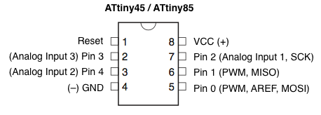
Such as physically incorporating a ATtiny85 in the sensor unit that collects the data and communicates it to the main MPU via one of the communication buses (SPI or RS232). The 8 pin ATtiny85 can sometimes be had for under fifty cents.

attiny45-85.png
 
Yes, that's what I meant at the end of my post. Have the display on the bars be just a display device. This would also help with the wiring as all the sensor wires and even throttle control wires would be kept close to the controller. The cost of these Arduinos , rounded off, is zero. The soldering and making a little carrier board for the various tidbits is where the work is. Voltage regulator ( I used a lm317hv , works great ) voltage dividers, filter caps is the tedious work. I used a promini and mounted it in a 3d printed box with it's programming connector sticking out of the back, to make reflashing fairly easy. You end up doing the flash-remount-ride-change-software- loop many many times on projects like this. Lucky you can reflash these micros thousands of times before they wear out!
 
Ecyclist said:
Any success with VESC and pedelec?

This project is mainly intended for the Cycle Analyst, not VESC / pedelec, though you can probably use the proposed units with the VESC or any other controller. You might have to alter them to suit it's specific input needs.

But so far nothing has been coded yet--about a month and a half after my last post above, seriously bad life stuff started (Kirin and Yogi both died and I lost my world connection) and has kept me away from it; see most recent pages in my "blog" thread linked in signature for details. I am still intending to get back to it but any form of motivation to do anything at all is only now beginning to resurface....
 
Justin_LE at Grin has finally implemented torque-controlled startup from a complete stop for the CA in v3.2b2
https://endless-sphere.com/forums/viewtopic.php?f=4&t=37964&p=1711610#p1711559

So my first Nano Tidbit idea is no longer necessary for the CA. It can still be developed for controllers that have no PAS/torque sensor ability (just throttle), so they can be used for that without the CA. Once it actually gets developed, of course. ;) :oops:
 
amberwolf said:
Justin_LE at Grin has finally implemented torque-controlled startup from a complete stop for the CA in v3.2b2
https://endless-sphere.com/forums/viewtopic.php?f=4&t=37964&p=1711610#p1711559

So my first Nano Tidbit idea is no longer necessary for the CA. It can still be developed for controllers that have no PAS/torque sensor ability (just throttle), so they can be used for that without the CA. Once it actually gets developed, of course. ;) :oops:
If we will look at things like that we can as well stop building electric bikes and buy them in stores.
There are developers on the VESC Project forum working on incorporating PEDELEC into VESC.
I'm not that good with programming microcontrollers, but I designed and build the sailboat race starting machine that runs on Arduino Nano. I would like to see VESC with PEDELEC build-in. Unfortunately I can't help with VESC project because it's way over my head. If this is a dead end I will get my ass in gear and build a sub controller based on Arduino Nano and connect it to VESC.
 
I'd still like to do all these things, I was just pointing out that the CA can now do what that one was intended to do, so anyone using the CA with that new firmware (3.2) won't have to use one to bypass the old CA firmware limitation of essentially requiring cadence readings for the torque sensor to be active.

(I haven't tried the new FW yet, so I don't directly know how well it works, but reports are good so far).

If you would like to help with this project, I'd certainly appreciate it--I haven't yet learned enough programming to do anything useful yet. :oops: I know what is needed (just not how to do it).
 
Back
Top