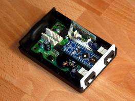
Arduino Nano Cycle Analyst (and other) companion TidBits

neptronix said:
Would much rather program in straight procedural C code than learn ardunio's variant of it though.. perhaps there exists an aftermarket compiler or transpiler.

Everything I’ve done with arduino has been straight C... My projects haven’t gone beyond reading IO, logic functions, loops, and integer maths, but have all compiled without drama. Just needed to learn the arduino library functions for reading and writing to the hardware, which were far easier to learn than than directly writing the registers etc.
 
rowbiker said:
Remember that the CA supplies unregulated 10VDC at a very limited current for the PAS and torque input sensors. It's good enough to directly power the pickups I've encountered, including the TDCM bottom bracket.
Yes...but as you pointed out, the higher voltage your system, the lower the current the CA can output without overheating it's regulator, and effectively blowing up the CA. (it doens't usually kill the MCU, but it takes out the regulator and sometimes other bits). I'm running at the highest voltage (14s) that's safe to even use a TDCM/etc on there as it is.

(I blew up my first CA essentially on installation, a 16s (IIRC) system because there was no warning about this on the CA itself, and if it was buried in the manual somewhere I didn't see it...it should be something tagged *on the PAS connector*, but AFAIK despite suggesting this years ago when this happened to me, they've never bothered. :/ )


I'd prefer to completely avoid that possibility, and I'd rather have an independent power supply for the Nano from the traction battery. (especially since it is likely I'm going to end up with more than one of them doing various things by the time I'm done, though some fucntions can be combined into one, some aren't related and are better off on a separate one).

I do have my lighting power avialalbe, which is 16.4v full and gets as low as about 14v worst case before I recharge it (usually still over 15v). The 7805, while not very efficient, would work off of that, and I probably have a bajillion of them (well, maybe only a quarter of a bajillion) in various saved bits of junk (including old dead controllers). I guess it's main benefit is being non-switching it will have a very clean output when running off a battery that is not being used to run a motor. The disadvantage of doing this is it then "connects" my lighting and traction systems via the Nano boards and all the sensor wires to/from the CA. IIRC I already have a common ground, but I'm not sure because I deliberately set out to correct that at one point some years back, and I no longer remember the exact wiring of the trike. (I really should make a complete diagram :oops: ).
 
neptronix said:
I am actually not a fan of the CA V3 at all due to throttle lag i've experienced in many setups using it.
I'm not sure if that's a matter of tuning the CA V3 better or an inherent quality of it's programming.
Once I set it up completely, I've never had any lag***...but I also always set all the throttle ramps to 99v/s (whatever the max is) so that it's essentially instantaneous change. If you don't change the ramping then it will change at whatever the default ramp rate is, however many volts per second. If it's 5v/s, it will take at least half a second to go from a typical minimum throttle to a typical maximum.

***there are bugs in the code when using High Range mode that lead to certain types of delays under certain circumstances with certain setups, but it's not a "lag" so much as a huge delay (about 8 seconds!), sometimes in the form of a ramping of response. But this doesn't happen normally.


I also want 3 speed switch capability, like the old school infineon clones.. but the CA does not do this easily.
Have you ever tried using the Preset function? It can change various limit / etc parameters all at the same time this way if you like, and conveniently there are three Presets available. ;)

Probably better for the above parts to go in a different thread (like the CAv3 "beta" thread, etc), but the below stuff is relevant.


Would love to see what you come up with, and i'm considering learning arduino myself because i'm thinking about building products outside of the EV realm using the ATMegas.

Would much rather program in straight procedural C code than learn ardunio's variant of it though.. perhaps there exists an aftermarket compiler or transpiler.
The latter I have no idea about. Never even heard the last word before. :oops:

I have avoided arduino despite my curiosity and my need for *something* to do things without complicated analog circuitry (taht I will never get around to building)...because it's programming, and I really just don't "grok" it very well. I do alright with I/O, but the processing part...especially the math stuff, tables, databases, all that stuff--that is where my head spins round and falls off. :lol:
 
LewTwo said:
In the Arduino development IDE the Nano connects to the PC via a terminal window.Just 'print' the results there :D
I guess I have a huge amount to learn...I didn't even know there was two-way communication in that window, I thought it was just a results window to show what was happening (like in many "firmware flashing" programs). :oops:


You will find that the "print" statement (wait I think that they changed it to function a couple of years ago) has the ability to format your 'integer' values to something more like you are expecting (like decimal values between 0 and 5 volts).
OK. Sounds like I'll have to be reading the "manual" (wherever that is--I'll find it) a bunch before I go forward any further. This may take a (long) while. :(


Just consider the ADC and PWM to be 8 bits. That means that you will have a resolution on 0-5 volts of about 0.02 volts. I think that should be adequate for your purposes.
I hope so. I don't think it will matter as I am not trying to hold a precision torque or speed or anything, just trying to get the ******* heavy trike started moving without either using a throttle blip to start it every time, or hurting my legs/etc every time. Most people just tell me "just use the throttle to get started" but that's just not good enough. ;) There really isn't a good reason not to have the *option* to do this right in the CA itself.... (sure, it shouldn't be the default mode....but it should be there--it actually was in some old beta version but that's not available anymore). (I bet that as soon as this project is finished, a new CA3.x firmware will come out that does allow it and makes it unnecessary :lol: ).
 
LewTwo said:
I was thinking they (PAS and Speedo) were a magnet passing a pickup coil. I had not thought of them triggering a switch (aka Hall effect transistor). That makes sense considering how the throttles work. That should simply things a bit. In that case duration may be the only gotcha to overcome.
The speedo is indeed a magnet passing a reed switch, but the CA has a pullup to 5v on one end of that, and the other is grounded. So the only thing to worry about is debouncing, potentially. But I can use a hall sensor right next to the CA's sensor to use the same magnets and get a completley separate speedo signal cleanly if it makes things easier in the code. :)

Technically I could use the halls in the motor, too, but the consequences are too great (though risk is small) for a phase/hall wire short in a motor cable failure, which would take out the Nano and potentially other things (controllers get killed by this often enough when noobs don't use torque arms and get axle spinout and wire damage).

The PAS is probably a hall already, but I don't know. Even if it is, it's could be done the same way as the motor halls--just grounding the output wire, not outputting a voltage, so a pullup to 5v is needed inside the reading device (CA in this case).
 
amberwolf said:
I'd prefer to completely avoid that possibility, and I'd rather have an independent power supply for the Nano from the traction battery. (especially since it is likely I'm going to end up with more than one of them doing various things by the time I'm done, though some fucntions can be combined into one, some aren't related and are better off on a separate one).

Agreed.

amberwolf said:
I do have my lighting power avialalbe, which is 16.4v full and gets as low as about 14v worst case before I recharge it (usually still over 15v). The 7805, while not very efficient, would work off of that, and I probably have a bajillion of them (well, maybe only a quarter of a bajillion) in various saved bits of junk (including old dead controllers). I guess it's main benefit is being non-switching it will have a very clean output when running off a battery that is not being used to run a motor. The disadvantage of doing this is it then "connects" my lighting and traction systems via the Nano boards and all the sensor wires to/from the CA. IIRC I already have a common ground, but I'm not sure because I deliberately set out to correct that at one point some years back, and I no longer remember the exact wiring of the trike. (I really should make a complete diagram :oops: ).

While it makes all kinds of sense to use an existing lighting circuit with its already (usually) lower voltage, my main concern is that it might not work for a lot of folks. I have a history of riding a lot of non-assisted vehicles, so over the years I've developed a very portable lighting system that's based on me (helmet lights, etc.), not the bike I happen to be riding. Since the solution you're designing here is very vehicle based, and every one of them will have a traction battery, I think the "independent power supply" you mention above is a great idea. This is supported by the fact that you can now typically get these little DC-to-DC converters for under $10. My main reason for getting the power from the CA is to make the wiring as simple as possible, but as you said, NOT at the cost of blowing up parts of the CA. And yes, diagrams are good!
 
Took me a while to clean out some of the cob-webs and find this:
http:www.keywild.com/arduino/Arduino_Nano_Stuff.zip
It is a collection of some reference material I collected when working with the Nano. You may find some of it useful.

There are three ways to power the Nano
1) via the USB bus. In that case the voltage may be anywhere between 4 and 6 volts dc depending on the computer you are attached to.
2) You can feed it between 7 and 12 volts via the VIN pin. In this case the power goes through the 5 volt regulator on the bottom side of the board. This is the MOST reliable source.
3) You can 'backfeed' your own regulated 5 volt DC to the 5 volt pin. NOT recommended !

This is where the some of the ADC problems start if one is using the on board 5 Volt voltage reference. Say you going along fine developing your project on your desktop PC which just happens to out put 5.5 volts on the USB plug. Then you switch to a laptop for some remote testing. The laptop puts out 4.5 volts on the USB plug. Suddenly all your ADC reading are wrong.

The good news is that if you ALWAYS power the Nano via the VIN pin with 7-12 volts DC then your 5 volt reference should be consistent. If you look at the schematics (included in the zip file above) then you will see a circuit that switches from USB power to VIN power when VIN exceeds 7 volts or the USB voltage. Sometimes people have been known to cut the trace to USB power to force the Nano to ALWAYS use VIN. Maximum power available is 200 milliamps.

Another point of interest: maximum power draw for the Nano (by itself) is 19 milliamps. I forget where I found this little tid bit but best I remember it was hard to pin down (pun intended).

One other warning:
The Nano has a 'common' ground with your development computer via the USB plug.
Avoid 'Magic Smoke' by making certain that there is NO path between the positive voltage side of your traction battery and the computer.
 
rowbiker said:
While it makes all kinds of sense to use an existing lighting circuit with its already (usually) lower voltage, my main concern is that it might not work for a lot of folks. I have a history of riding a lot of non-assisted vehicles, so over the years I've developed a very portable lighting system that's based on me (helmet lights, etc.), not the bike I happen to be riding. Since the solution you're designing here is very vehicle based, and every one of them will have a traction battery, I think the "independent power supply" you mention above is a great idea. This is supported by the fact that you can now typically get these little DC-to-DC converters for under $10. My main reason for getting the power from the CA is to make the wiring as simple as possible, but as you said, NOT at the cost of blowing up parts of the CA. And yes, diagrams are good!

If it weren't for the vulnerability of the CA's regulator, I really really would prefer to just use it for the power; it would make things easier because I could even make it so the Nano board would install right inside the CA casing, too, so no new housing would be required.

I just don't know exactly how much current is available from it at my full charge (57.7v), and then exactly how much current the things already running from it take (the CA itself, the two COT throttle units, the TDCM BB sensor; I think that's all right now), in addition to the listed 19mA the Nano could take (not counting any additional circuitry I end up having to put on it for I/O buffering/etc).


I tried for some time to find an actual specification for max current on the CA's 5v / 10v outputs, but I could not. The only info I can find are notes (including within the manual) that state it's best to stay below 60v max or 52v nominal packs if using a torque sensor powered by the CA itself, and that those sensor can draw as much as 20mA. Well, if 20mA from teh torque sensor is enough to bring the CA down where it could be damaged above 60v, what happens if you double that current draw with a Nano running at full power? Since the CA3 can normally handle 150v without the load of the TS, and it's down to 60v (less than half!) with one, then I don't even know that it would survive the load of the TS plus Nano with a 12v battery system, which is about the minimum (maybe below) to properly run the CA and let it save data on shutdown. :(


I've been poking around the internet for an hour now, and I actually can't even *find* a DC-DC that converts from around at least 30-100vdc (so that it could easily be used for others with a wide variety of battery packs) to 5vdc (or some range thereabouts). I know they're out there, I have seen them a lot...but I can't find one now that I want to actually order one. I can find thousands of things with 5vdc out, but none of them go higher than about 40vdc.

I know that I can use an LM317 with some big resistors on the input, and a 7805 on that, just like many controllers do...but it's inelegant and wasteful of power and gets pretty hot in a small enclosed space. And I'd have to build it "deadbug" style, or have PCBs made.

I found a few DIY projects with gerbers, parts lists, schematic, that goes from 60vdc in to 5vdc out, so it would work for me, barely any margin, but I'd have to locate all the parts and build it (including SMD stuff that I would probably not be able to correctly solder), after having the PCB made. Not an option for most people (even those willing to solder a few wires from a Nano to their CA), and I wouldn't be able to make them for other people.
https://www.electronics-lab.com/project/60v-5v-dc-dc-step-converter-using-lmr16030/
https://www.electronics-lab.com/project/60v-input-5v-3a-output-dc-dc-converter-industrial-automotive/
https://www.electronics-lab.com/project/60v-to-5v-3-5a-buck-converter-with-usb-output/

I"m still looking around...but the search functions of the cheap and/or quick-to-get sites (amazon, aliexpress, etc) suck and can't find their own home page much less anything useful ;) so I've been using google to search them instead, with just about zero luck. Normally I'm really really good at finding stuff in the first few hits, but not today.

Of course, there are quite a few AC adapters for USB output that I've run across that happen to run on my battery voltage range...but they don't work on much lower than around 50v input, sometimes 45v, not usually 30-40v, which means they aren't useful for anyone else that wants to run these projects (though I guess they could just run them off the CA power, as their battery voltage isn't high enough to present a risk...I'd rather be able to provide a complete open-source documented project they can just get the linked parts of and program and wire in and go. :) ).


Well, enough griping, I'll go poke around some more for a DC-DC that will do it. :)
 
LewTwo said:
Took me a while to clean out some of the cob-webs and find this:
http:www.keywild.com/arduino/Arduino_Nano_Stuff.zip
It is a collection of some reference material I collected when working with the Nano. You may find some of it useful.
Thanks! At the least, the pinouts are good for drawing over, and the Atmega reference is useful for making sure the actual IO would do what I want electrically, and for how the internals actually work if i run into some wierd problem. (or rather, *when*...).


There are three ways to power the Nano
1) via the USB bus. In that case the voltage may be anywhere between 4 and 6 volts dc depending on the computer you are attached to.
2) You can feed it between 7 and 12 volts via the VIN pin. In this case the power goes through the 5 volt regulator on the bottom side of the board. This is the MOST reliable source.
3) You can 'backfeed' your own regulated 5 volt DC to the 5 volt pin. NOT recommended !

This is where the some of the ADC problems start if one is using the on board 5 Volt voltage reference. Say you going along fine developing your project on your desktop PC which just happens to out put 5.5 volts on the USB plug. Then you switch to a laptop for some remote testing. The laptop puts out 4.5 volts on the USB plug. Suddenly all your ADC reading are wrong.

The good news is that if you ALWAYS power the Nano via the VIN pin with 7-12 volts DC then your 5 volt reference should be consistent. If you look at the schematics (included in the zip file above) then you will see a circuit that switches from USB power to VIN power when VIN exceeds 7 volts or the USB voltage. Sometimes people have been known to cut the trace to USB power to force the Nano to ALWAYS use VIN. Maximum power available is 200 milliamps.

I've been looking for a little DC-DC to power it all from, as noted in the post just before this one, no luck yet. If the 12vdc is an absolute max it's a little harder, if that is a "soft" limit it's a little easier, as the regulation of the cheapest little DC-DCs might not be as perfect as I'd prefer. Might come down to the inelegant resistor --> LM317 then to the VIN pin. I guess if I end up with any significant external components (that can't just be installed on the edges of the Nano board), I would just have a PCB made for all of the parts that can then connect to the Nano with the board-edge header.
 
Do you think that the +5 or in my case +6 coming out of the throttle 3 pin connector from the KT controller has enough power to feed an Arduino ? That would be the easiest solution, to feed that into the Vin of the nano, that way voltage spikes would be somewhat controlled by the nano voltage regulator. Otherwise is there a simple circuit to get +5 at maybe 100ma from a 41 volt battery? The cheap dcdc buck converters don't like high voltages like that unfortunately.
 
Poking around I found there's another similar regulator to the LM317 called the LR12
https://www.microchip.com/wwwproducts/en/LR12
https://ww1.microchip.com/downloads/en/DeviceDoc/20005364A.pdf
http://ww1.microchip.com/downloads/en/Appnotes/AN-H40.pdf
that cna around 12v up to 100vdc input, and output from 1.2 to 88v, *and* has current limiting (presumably to prevent just blwoing it up wiht too high a load). Only goes to 50mA max output, but that should be enough for one Nano and any associated stuff. Use a separate one for each Nano where needed. Is a little bitty TO-92 3-pin case, thru-hole, so easy to use even mounted right at the edge connector if necessary. Only *requires* two resistors (for voltage adjustment) and an output filter cap. Requires 12v minimum difference between input and output, shouldn't be an issue. It's also thermally limited, so it will reduce output if it gets too hot instead of blowing up.

Looks like there's a newer version
https://www.mouser.com/ProductDetail/Microchip-Technology/LR12N3-G/?qs=CfS20XsW4%2FBAbzaA1nmgaw%3D%3D
LR12N3 in the same case but has 100mA output (EDIT: my mistake, just read the page wrong--still 50mA). They're less than $2 even in singles--$1 each at 25qty. This might be worth buying a handful just to have around for little things like this.


Another one in a TO220 package (larger) is this
https://www.mouser.com/ProductDetail/Texas-Instruments/TL783CKCSE3/?qs=7kv20MEVUlgqq%252Bl8ftXLuw%3D%3D
which can do 150v input and adjustable well within anything we'd want it for on the output, and 700mA max current.
Couple bucks each in singles.


Another TO220 package is this
https://www.mouser.com/ProductDetail/Texas-Instruments/LM317HVT-NOPB/?qs=X1J7HmVL2ZFyvDtHey14xA%3D%3D
which is a high voltage ;) version of the LM317, which works up to 60v max input. That's a little close for comfort for me, but it would work for my application. 1.5A output max. About $2.50 in singles. Nifty thing about this part is you could directly replace the LM317 in many controllers used for 48v and below packs (not sure I'd use it in a 52v pack) and ditch those two big resistors on the input that generate so much heat. Don't know how mcuh heat this chip would generate on it's own in that instance, but I would guess it is less than the resistors do.
 
My favorite shopping places are Amazon and Ebay. Ebay's search engine is pretty good but Amazon's is the absolute worst on the internet. So when I find something 'interesting' on Amazon I tend add it to a shopping list even if I do not currently have a use for it.

Try some of these links:
https://www.amazon.com/dp/B082QXGR5D

https://www.amazon.com/dp/B07DKXKQNS
https://www.amazon.com/dp/B078XRFQTM
https://www.amazon.com/dp/B082FWJPVH
https://www.amazon.com/dp/B07G29XTCL
https://www.amazon.com/dp/B07BRH96BZ

The first one would be my choice :wink:
Note that one would need that 'silly white goop' as there is no other mounting provision.
Might stick one of these in my new battery box just so I have 12 volts DC available.
 
LewTwo said:
My favorite shopping places are Amazon and Ebay. Ebay's search engine is pretty good but Amazon's is the absolute worst on the internet. So when I find something 'interesting' on Amazon I tend add it to a shopping list even if I do not currently have a use for it.
Yes; I have a lot of list of "Hmmm..I might need one of those someday...but I know I'll never find it again, so...". ;)

Thanks for the links. The first one is the best option, and is most like the ones I was looking for that I have found previously, but I do wish they hadn't sanded off the chip numbers. There are quite a few DC-DC boards like these that various ES members have ordered (from where, I don't know) that end up having chips not actually capable of the voltages/etc that are claimed, and/or can't do the *difference* in voltage needed and/or at the power level needed, but that don't have protections against trying it, so they go poof. :(

If I could see which chip it used (there are several with the same package and pin count, IIRC) I could find out what it was *actually* capable of before buying and testing one. :)

It's not that I don't trust the seller...but, well, I don't trust them (or most sellers regardless of what platform they sell on), because they don't even have the right units in the physical dimensions in the image for them. I'm absolutely certain it isn't 55 centimeters long, for instance. :lol: (the units *are* correct in the text; don't know if the actual numbers are)


Note that one would need that 'silly white goop' as there is no other mounting provision.
I have Kapton tape I can wrap around it, and doublesided foam tape to hold it in place, for "beta testing" before permanentizing anything that much.

The other versions, while lower voltage, would still work, and though they are larger they are also encapsulated such that they are likely water resistant and do have mounting options built in.
 
Decisions, decisions.

I am still considering options, as there is no hurry yet, but I may just go with one of the linear regulators (LS12 or TL783) from Mouser, partly because it's a lot smaller, and a lot cheaper (if I buy a handful and use one per Nano, for instance), and there's less worry about quality of build / parts / etc. 25 of the LS12s is just under $29 shipped, will take up to a couple weeks to get here once ordered, if I go that way.

PCBway (I think it's called) and other such places seem to often have specials for $2 a PCB for small ones, so once I have a complete hardware design including the regulator and resistors and all the I/O buffering (RC filters for PWM outputs, op-amps on analog inputs, OC transistors on digital outputs, etc, if necessary), then I could have PCBs made for holding all those that would then just solder onto the Nano via the edge headers on the Nano. (like other "shields", I think they're called). Then if others wanted the same board, they can just use the same files to have such a place make them the same PCB, etc.


I guess first need to at least pseudocode the rest of the TorqueSensor-Start-From-Standstill module, then hook up the test bench setup for a CA3 and TDCM and PSU, etc., to see if it actually does anything. Then worry about which regulator to use.

I also need to draw up the basic schematic for the Nano plus the above to be sure what pins will be used for what, and make sure there *are* enough pins (almost certainly will have extra).
 
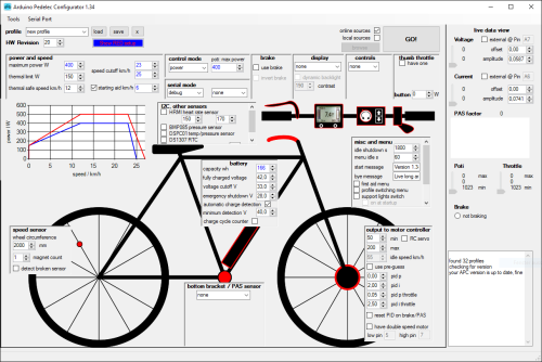
Do you know the "Forumscontroller" project? It is arduino based and implements PAS and torquesensor processing, current control, various displays are supported and many other features are implemented. It works well with the VESC or any other controller with an analogue voltage throttle input. A graphical interface helps you to configure the system.

It's open source, so perhaps you can get some inspiration from it :)

https://github.com/jenkie/Arduino-Pedelec-Controller

regards
stancecoke

schematic:
https://www.pedelecforum.de/wiki/lib/exe/fetch.php?media=elektrotechnik:forumscontroller:fc_schaltplan_2.3.pdf

fetch.php


fetch.php
 
stancecoke said:
Do you know the "Forumscontroller" project? It is arduino based and implements PAS and torquesensor processing, current control, various displays are supported and many other features are implemented. It works well with the VESC or any other controller with an analogue voltage throttle input. A graphical interface helps you to configure the system.

Well that is interesting ... or at least it was until they mentioned that other operating system:
The Windows software “Arduino Pedelec Configurator” is used as standard for programming,
:cry:

UGH ... my German comprehension is worse than my chi-english comprehension.
Version 1.5 uses a Nano as well.
I wonder if there is a list of features/improvement for the various versions.
 
LewTwo said:
that other operating system
You don't need the graphical configurator, you can edit the config.h by hand, of course.

LewTwo said:
my German comprehension is worse than my chi-english comprehension
You can use deepl.com for translation of the german wiki, it gives much better results than google translate...

LewTwo said:
I wonder if there is a list of features/improvement for the various versions.
https://www.pedelecforum.de/wiki/lib/exe/fetch.php?media=elektrotechnik:fc_changelog.pdf

regards
stancecoke
 
About a year ago I was working on a similar project - https://github.com/thorlancaster/electric-bike-controller. It was a much more complex project than this. It served as a replacement as a cycle analyst, not an addition to it. It also communicated across several Arduinos via an opto-isolated Serial protocol (Should have used CAN in hindsight) but you might find it useful. The relevant code is in the "MasterControllerV3.0" folder.

Re - The voltage regulators. Don't use a linear regulator to convert the battery voltage down to 5v. You will be wasting 10x more power than your circuit is consuming and you won't be able to draw much before the regulator overheats. I've had good luck with the "lm2596hvs" modules that are sold everywhere on Ebay, Amazon, etc. Just make sure to order a genuine IC from Digikey, ETC. if you want to run over 40 volts, as the one provided is likely counterfeit and will likely explode around 50v taking other stuff out with it. If you are making a PCB, the LM5107 is a great choice. I use it in my controller prototype and it doesn't even get warm, and it's good up to 100 volts.
EDIT: I meant LM5017 not LM5107

Re - PWM for throttle control - Everything will be a LOT easier if your controller has current throttle. If the controller supports the StanceCoke firmware, I'd try it. To generate a throttle signal, take the analog output pin and filter it through a resistor and capacitor. I've had good results with a 1kohm resistor and 22uf capacitor but you could probably go higher on the cutoff frequency (Smaller Capacitor / Resistor) and still get good results.
Pins 3 and 11 of the Atmega328 can run at a much higher PWM frequency (10s of KHz IIRC) if you change a prescaler register, making the filtering components smaller. I don't think this will be needed though.
 
I have an off-the-wall concept for analog outputs: digital potentiometer
Most of these are resistor ladders with anywhere from 100 to 1024 rungs (pun intended). The current limits are extremely low so one would likely need to feed it to a op-amp or transistor to be useful.
 
You don't need near that much bandwidth unless you were trying to play music through the throttle line. Sure it would work but it'd be 5x the board space and cost at least 10x as much as the low-bandwidth RC filter.

If your controller could respond to a 100hz bandwidth throttle signal, the RC filter would be a good idea. But most Chinese controllers filter the input, limiting the bandwidth to somewhere around 2-5 Hz.

Even if you were trying to play music, fast PWM and a 4th-order filter would use less components. Op amp would still be needed though.
 
thorlancaster328 said:
About a year ago I was working on a similar project - https://github.com/thorlancaster/electric-bike-controller. It was a much more complex project than this. It served as a replacement as a cycle analyst, not an addition to it. It also communicated across several Arduinos via an opto-isolated Serial protocol (Should have used CAN in hindsight) but you might find it useful. The relevant code is in the "MasterControllerV3.0" folder.
Thank you--I'll take a look at that. :)


Re - The voltage regulators. Don't use a linear regulator to convert the battery voltage down to 5v. You will be wasting 10x more power than your circuit is consuming and you won't be able to draw much before the regulator overheats. I've had good luck with the "lm2596hvs" modules that are sold everywhere on Ebay, Amazon, etc. Just make sure to order a genuine IC from Digikey, ETC. if you want to run over 40 volts, as the one provided is likely counterfeit and will likely explode around 50v taking other stuff out with it. If you are making a PCB, the LM5107 is a great choice. I use it in my controller prototype and it doesn't even get warm, and it's good up to 100 volts.
If this project was *just* for me, I'd be using the lighting voltage (14-16.4v) to convert to an input voltage for the Nano (with a 7812 most likely as I have a whole bunch of those around here in various things), and not have to worry about all this. But since I would like this project to be easily usable by "anyone" that is willing to do the wiring and such, but that won't really likely know enough about things to deal with design/etc., and probably can't do SMD work...I would like, if possible, to make something very small and very simple that is all thru-hole parts so it is as easy to put together as the wires themselves.

I don't want to link to DC-DCs taht people will have to take parts off of and add new parts to (which I'm unlikely to be successful at myself), though I do know of the problem with those 2596 boards; it's been posted enough around here. :)

Though so far I have been unable to, I'd prefer to find a reliable 100v-capable DC-DC that is widely available and "cheap" (less than $10), so that "anyone" can just use the BOM I'll have eventually to just buy and wire this all together, upload the code to the Nano, and ride. :) 60V is probably going to have to do, realistically.

If I have to, I'll design a small PCB that people can order from PCBway or similar places, to hold parts to make the DC-DC and any I/O stuff that is necessary, but it'll all be thru-hole stuff if so.

BTW, the LM5107 info I can find says it is a gate driver.
https://www.ti.com/product/LM5107
How would that be used to make a simple DC-DC? (I know basic electronics, and "misuse" things successfully a fair bit of the time, but I R Not an Engineer ;) so I don't know what to do with that kind of chip other than it's stated use).

I don't expect to have to use much current in this device, if it only takes ~20mA for the Nano, and to likely overestimate we'll say the same again for all the I/O extras, for a total of 40mA for the entire "device". I know that at the high voltage input and very low voltage output there's going to be a lot of wasted power, but i"ll have to test out what heat and losses there will really be.


Re - PWM for throttle control - Everything will be a LOT easier if your controller has current throttle. If the controller supports the StanceCoke firmware, I'd try it.
Even if mine did, that won't work for the goal of the project--this has to be something that "works" with the majority of people that need to use this, without requiring specialized controllers or types. If someone has something that works in an uncommon way and wants to still use these tidbits, they will have to adapt them to their circumstance. ;) But my goal is to make them work for me, with my "random" collection of stuff that's on the trike right now, which means they'll probably work on anyone else's average stuff. ATM I have one Grinfineon and one unknown generic, each driving a completely different kind of hubmotor.

Eventually I will finish my pair of Lebowski-Honda IMA controllers (am 99% done with the first one), which AFAICR do use "torque" (current) throttle control, but the first bit of this project (torque sensing BB plus CA giving pedal-torque control from a complete stop) should work the same way with those as it will with the others...because if I do it the way I want to, it won't actually talk to the controller at all. It will only talk to the Cycle Analyst, which will then do what it always does...it will just do it from a complete stop, rather than having to be moving a little bit first.


To generate a throttle signal, take the analog output pin and filter it through a resistor and capacitor. I've had good results with a 1kohm resistor and 22uf capacitor but you could probably go higher on the cutoff frequency (Smaller Capacitor / Resistor) and still get good results.
That's the initial plan, based on this project:
https://endless-sphere.com/forums/viewtopic.php?f=2&t=87116
which is my inspiration for starting this whole thing. :)
 
LewTwo said:
I have an off-the-wall concept for analog outputs: digital potentiometer
Most of these are resistor ladders with anywhere from 100 to 1024 rungs (pun intended). The current limits are extremely low so one would likely need to feed it to a op-amp or transistor to be useful.

I considered this method for the throttle output, (not sure if it's in any of the posts above or not, dont' remember if I wrote out all the optional paths I thought about) because they're "directly" controllable from the Nano "SPI" pin/port/whatever, IIRC, and more precisely controllable. I even have a Maxim digipot somewhere around here that I was going to use years ago to build a "torque sensor" throttle that would have worked about like BeamTS, for CrazyBike2.

But it is much simpler to use an RC filter on a PWM pin, and requires less parts and is less work to wire up and cheaper. :) So it is more likely I'll be able to finish this project if i do it this way, at least for the first iteration. After it "works", then maybe it'll get updated with that as an option.
 
amberwolf said:
BTW, the LM5107 info I can find says it is a gate driver.
https://www.ti.com/product/LM5107
How would that be used to make a simple DC-DC? (I know basic electronics, and "misuse" things successfully a fair bit of the time, but I R Not an Engineer so I don't know what to do with that kind of chip other than it's stated use).
Sorry, I meant LM5017. It's a buck regulator good for 600ma and 100 volts in. Given that it has a thermal pad on the bottom it's quite difficult to solder with an iron though, near impossible if new to soldering. Hot air gun is best way to place it. However you can also leave a few small through holes in the board and solder it that way. Add solder to one hole until you see the solder start to come up the others.
 
That's a nifty chip, and in the hands of the right designer and builder, would be great.

But the way my hands work (or don't, really), there's no way I could solder the little SMT leads (sometimes I have trouble with thru-hole stuff, these days). If I managed to not bridge them all together, I'd probably burn it up from overheating. :lol: :oops: I expect that's going to be a problem for a lot of people that would like to use these little tidbits I hope to design, if they have to build all the stuff other than the Nano "from scratch".

Worse is that it appears to require a lot of external components and signifcant PCB space for everything (assuming thru-hole parts vs unsolderable-by-me SMD stuff). I only took a teensy poke around google but didn't find a prebuilt board for any reasonable price, which is another issue. Just this one
https://www.ti.com/tool/LM5017EVAL
for $25 (plus whatever shipping they charge).
and this
https://www.mouser.com/ProductDetail/Texas-Instruments/LM5017EVAL-NOPB/?qs=vobMBmnAsJFdjFiyaDcRbQ%3D%3D
for $30 (plus shipping)


I suppose if there were enough people that signed up for a list and prepaid for all the stuff and shipping, I could have one of those PCB places actually build the board that goes on each Nano for the different tidbits and then send them all out to the list once they arrived and were done. But if any of them didn't work (as I would not have the time and ability to test them), then whoever got one of those would be out of luck unless they could fix them themselves, or there was a large enough cost-buffer margin in the order to buy a bunch of extras for that purpose and pay for shipping them out. :(

Not really something I want to get into--I've seen just about every way a "group buy" can go wrong, and dont' really want anything to do with one. ;)

With the linear regulators and all thruhole parts, just making a PCB file set and BOM for poeple to make their own isn't too much work, even if it is very inefficient.

If you can think of an easy way to do something like that with this chip (or something similar), I'm all ears. ;)
 
While you are considering design features, consider a optional button for throttle 'cruise control' :)

Regards to powering the Nano:
It sounds as if the Nano's on board 5 volt regulator (5-12 volt DC input) would provide sufficient power.
If that be the case considering separating it into to projects: one for the nano and one for the power supply

You indicated you already have a secondary voltage source for lighting you could use. Many others are likely in the same boat.
Or they could use one of the previously listed Step-Down sources.
Or they could build the power supply project.
More choices = flexibility :wink:
 
Back
Top