Arlo's power stage Leaf controller runs and drives page 103

Lebowski said:
Under windows with labview 2013 you probably need ni-max to configure the rs232...

https://www.ni.com/getting-started/set-up-hardware/instrument-control/serial-connect
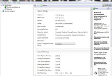
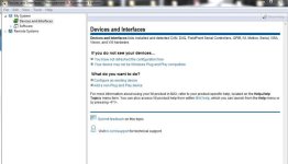
Here is what I get. The options for Rs232 or com or usb or anything simply are not there to chose from.

I will try another computer.
 

Attachments

  • labview2.jpg
    labview2.jpg
    48.9 KB · Views: 4,071
  • Labeview3.jpg
    Labeview3.jpg
    37 KB · Views: 4,071
Arlo1 said:
(...) Today is a day I have been waiting for for a LONG time! Its going in the car :)
I now have confidence in the system. (...)
Hey Arlo, super! Congratulations 8)
Persistence always pays off.
 
Thanks Njay. Its been a long road.
Today I got some no load measurements before attaching the gear reduction and lowering the motor in the car.. :)

7.1a at 444v for 3152.4 watts at 9090 rpm
[youtube]ryCmrmIqqAI[/youtube]
 
i just saw some of your yt videos

your crx is gonna haul some serious ass..

i wonder how may kw that nissan leaf motor can handle!

My sould ev is limited at 80kw...its bottom end toque is good.. top end is soft...

congrats ... i can only imagine the time and effort you put into it.. now you can enjoy the results..

what battery setup are you going with? is that planned yet or you havnt gotten that far..

-steveo
 
steveo said:
i just saw some of your yt videos

your crx is gonna haul some serious ass..
That's the plan :) Should weigh ~2100 lbs when done

i wonder how may kw that nissan leaf motor can handle!I worked the math and I think 716kw is doable for 10 seconds with a very stiff battery

My sould ev is limited at 80kw...its bottom end toque is good.. top end is soft...Soul EV? We love the soul EV just cant afford one. Wife wants one so bad.

congrats ... i can only imagine the time and effort you put into it.. now you can enjoy the results..

what battery setup are you going with? is that planned yet or you havnt gotten that far..

-steveo
Really looking at 2015 leaf batteries. I might buy 2 and use ~1.3 =1.4of them to get a real 30kwh of energy
The 2015 leaf battery has a higher C rating then older stuff. You can get them from 2-3k us from a Wrecker.
 
Arlo1 said:
steveo said:
i just saw some of your yt videos

your crx is gonna haul some serious ass..
That's the plan :) Should weigh ~2100 lbs when done

i wonder how may kw that nissan leaf motor can handle!I worked the math and I think 716kw is doable for 10 seconds with a very stiff battery

My sould ev is limited at 80kw...its bottom end toque is good.. top end is soft...Soul EV? We love the soul EV just cant afford one. Wife wants one so bad.

congrats ... i can only imagine the time and effort you put into it.. now you can enjoy the results..

what battery setup are you going with? is that planned yet or you havnt gotten that far..

-steveo

Really looking at 2015 leaf batteries. I might buy 2 and use ~1.3 =1.4 of them to get a real 30kwh of energy
The 2015 leaf battery has a higher C rating then older stuff. You can get them from 2-3k us from a Wrecker.

i think a leaf battery is a excellent option if your gonna use it under "normal" driving conditions....

but i don't think this will be the performance battery you may be after.. I would suspect beyond what the oem power limits some serious battery sag..

I have not read much about the 2015 leaf cell specs.. so i'm not sure.. would love to test a cell and compare it to a a123 20 ah pouch cell and even a 2.3ah cell ..
if i where you, i would get my hands on a chevy volt pack.. I think you could yield better power output.. and i love the steady discharge curve.. despite they are less energy dense the lipos

if you need some serious cell testing.. send me some lose cells.. I have some nice restive loads i can use at home to test..

-steveo
 
and it only took you 100 pages. not bad :)

i'm off to start a new design on a 48V, 200A DC motor controller for battle bots. yep.. another project haha
 
HighHopes said:
and it only took you 100 pages. not bad :)

i'm off to start a new design on a 48V, 200A DC motor controller for battle bots. yep.. another project haha
Brushed..... :(

In my defense I built about 5 different controllers in the 100 pages. The last one worked :) and the rest will as well.

;)

Thanks again. Hope to meet for a beer or coffee or EV ride one day.
 
Posted a video of the car running for the first time. Im going to keep all things for the leaf inverter install and testing on this thread from now on. Then in the not to distant future I have a lower voltage power stage coming back here. Stay tuned ;)
 
Damn. I spent the night plagued with latch-up problems in the driver circuits I have to debug this one last thing. When I am trying settings that might push things once in a while something triggers a latchup on one of the drivers. It seems to be any phase. This has been something I have noticed since day 1 using the ACPL333j But I'm not blaming the driver its likely something I have off a bit or wrong. I have read a lot about this and need to dig up the links but inductance in the circuit is one thing suggested to trigger it.
I was also wondering about having a ground plain above the drivers to shield them...
 
It's going to be awesome to see this thing running at full power :)

When you move on to designing the next version, I can give you some ideas to ponder for the DC link side if you are interested. I've done lots and lots of research in this area both physically and in simulation. I sorted out all the bumps found in a double pulse test and how to control them.
 
It should be noted all the protection (Desat zeners on the gate etc.) Saved me $1000s and 100s of hours just tonight alone!
Found this link... Reading it now.. Hoping for a golden nugget.

http://ww1.microchip.com/downloads/en/AppNotes/00763c.pdf
 
Here is another couple quick reads. http://www.intersil.com/content/dam/Intersil/documents/an11/an1108.pdf
http://www.ti.com/lit/an/slya014a/slya014a.pdf

I'm actually excited to solve this. I have to do another revision on the driver boards and I will add a diode from the gate to the positive of the caps from the isolated supplies as HH pointed out for over voltage protection on the gate of the IGBTs I need to make bigger and better grounds. And move the pins apart for the igbt gates a smidgen...

If I find something to change while fixing this problem I will try to add it to the design as well.
 
OK. Now I see 1 thing I am sure I should have done a little different.
I have the 5v supply for all digital stuff on the brain board which has about 18" sheilded of ribbon cable running from it to each driver board.
I have done a lot of reading and the drivers can latch up if the power lines move around or the driver ground goes below the actual ground and if the driver VCC goes above the actual 5v supply.

Think of it this way the signal for the PWM comes from the Brain in reference to the 5v supply + and - and with 18" of wire the inductance & resistance can make that jump around a lot. What I think the first thing I need is a Cap for the 5v supply on each brain board say 47uh? I have .1 uf decoupling caps at each driver but that's it.
I will also add diode clams to protect the signals so the signal can never go below - or above 5v +
While in there I will make sure my pull down resistor is a 4.7k and not the 10k I originally put in my notes.
I might also add a 4.7uf cap parallel to the .1 decoupling cap right at the driver.

Any input? I feel this is the right track to find the problem and any suggestions to solve it would be great.

To be clear I have a problem with something latching on I think its a driver as about 1 year ago I saw something like this and it was visible with the thermal cam I saw a driver heating up but cycling the power made it go back to normal. It only happens when the motor settings are off and it shakes around or looses sync. But what happens is the IGBT in which ever stage stays latched on and when I cycle power it goes away. Once in a while I happens during start-up as well... Seems to have gotten worse but that could be settings I have changed.

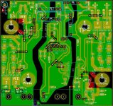
Here is a screen shot of the last revision and its what the driver board looks like ATM. I will be revising it again.
 

Attachments

  • Jan 2016 driver.JPG
    Jan 2016 driver.JPG
    120.3 KB · Views: 3,837
It should be noted all the protection (Desat zeners on the gate etc.) Saved me $1000s and 100s of hours just tonight alone!
the first BEvERAge is on you then ;)
 
I added 1 47uf cap to the 5v circuit on each driver board today. I also found 25 schotky diodes in my inventory and it turns out they are the best to protect the drivers from voltage fluctuations causign latching.
I have 1 phase done and hope to add then go the other two tomorrow and test it.
I will post a sch. Soon.
 
HighHopes said:
It should be noted all the protection (Desat zeners on the gate etc.) Saved me $1000s and 100s of hours just tonight alone!
the first BEvERAge is on you then ;)
Come visit. I'll get you anything I can on my budget ;)
 
Arlo1 said:
I added 1 47uf cap to the 5v circuit on each driver board today. I also found 25 schotky diodes in my inventory and it turns out they are the best to protect the drivers from voltage fluctuations causign latching.
I have 1 phase done and hope to add then go the other two tomorrow and test it.
I will post a sch. Soon.

Great project you have here!
If I may add to the 5 volt side of things, this is pretty basic stuff here, certainly compared to the other stuff in this thread.
Each chip or consumer should have a local (ie as close as possible) decoupling cap with a low as possible ESR, bigger caps have lower ESR but are not always practical, so high quality "low esr" types are desired.
In the 25 years of building and modding pro audio equipment I've grown a favour to the Nippon chemicon lxf and Panasonic FC and now FR series.
A 220uf per consumer would do in most cases, where you have the space (parallel bodged on the underside of the pcb) you could add a foil (such as a wima mkp series) or tantalum capacitor to get the really hf noise out.
Just poke around with the scope to see how flat your 5vdc is. (noise should be down to millivolt levels)
 
mrass said:
Arlo1 said:
I added 1 47uf cap to the 5v circuit on each driver board today. I also found 25 schotky diodes in my inventory and it turns out they are the best to protect the drivers from voltage fluctuations causign latching.
I have 1 phase done and hope to add then go the other two tomorrow and test it.
I will post a sch. Soon.

Great project you have here!
If I may add to the 5 volt side of things, this is pretty basic stuff here, certainly compared to the other stuff in this thread.
Each chip or consumer should have a local (ie as close as possible) decoupling cap with a low as possible ESR, bigger caps have lower ESR but are not always practical, so high quality "low esr" types are desired.
In the 25 years of building and modding pro audio equipment I've grown a favour to the Nippon chemicon lxf and Panasonic FC and now FR series.
A 220uf per consumer would do in most cases, where you have the space (parallel bodged on the underside of the pcb) you could add a foil (such as a wima mkp series) or tantalum capacitor to get the really hf noise out.
Just poke around with the scope to see how flat your 5vdc is. (noise should be down to millivolt levels)
Thanks for your response.
All "consumers" as you call them have a .1 uf X7R cap as close to the pins as possible. Then I put a 4.7f not quite as close to each consumer and a 47uF on every board. It seems fairly clean but its hard to test while under load as the big 600v cap covers all of this stuff. I have just updated the schematic and PCB files and I think when I build the new set I will be good to go. This did run great for a bit then slowly went down hill having intermittent problems that progressively showed up more and more until now It will not run. I have some more igbt modules on their was and I will order a new set of driver boards to build up tomorrow after I spend some time reviewing them.
 
Trying to understand something....

Avego mentions an optional output pull down resistor I have a pull down on the input and on the gate of the igbt it self. But I was just reading this.
Are they saying VBE = VCC2-3 diode drops? If so My supply is 15v and with that 15-3diode drops =VBE? So what would the diode drops be? .5v each? Putting VBE at 13.5?
Saying 13.5v/.000650 = 20769 But the equation shows [VCC2-3 * (VBE)]/650uA What does that meen?
Reason I ask is I don't have this resistor and I will add it to my design.
Output Pull-Down Resistor
During the output high transition, the output voltage rapidly rises to within 3 diode drops of VCC2. If the output current then drops to zero due to a capacitive load, the output voltage will slowly rise from roughly VCC2-3(VBE) to VCC2 within a period of several microseconds. To limit the output voltage to VCC2-3(VBE), a pull-down resistor, RPULL-DOWN between the output and VEE is recommended to sink a static current of several 650 μA while the output is high. Pull-down resistor values are dependent on the amount of positive supply and can be adjusted according to the formula, Rpull-down = [VCC2-3 * (VBE)] / 650 μA.

http://www.avagotech.com/docs/AV02-1087EN
 
I think when the 333J turns on, the gate voltage will be approx 13V due to the 3 diode drop thing if you have a 15v supply.
The resistor will keep a small load on the gate output and the gate voltage will stay at this Vcc2 - 3 diode drop. without the resistor and when current stops following
due the the fet been fully turned on the gate voltage may rise a little. I think that's all it is referring to.

I am about to use the 337J with has its output switch all the way up to Vcc.
 
The 3 VBE drop comes from the 3 bipolar transistors on the block diagram on the first page.
The pull-down at the gate-emitter should be enough if less than 20k, I don't think one more is needed on the driver output.
edit: I mean it if there is no current booster transistors between the driver and the IGBT; if you have then you may need the other pull-down (I didn't view your schematics)
 
peters said:
The 3 VBE drop comes from the 3 bipolar transistors on the block diagram on the first page.
The pull-down at the gate-emitter should be enough if less than 20k, I don't think one more is needed on the driver output.
edit: I mean it if there is no current booster transistors between the driver and the IGBT; if you have then you may need the other pull-down (I didn't view your schematics)
Yeah I was just trying to work the math they didn't word the calculation very well.

I do have boost transistors. So I should put a pull down on the driver output. My New board design has a spot that will work for it.
 
Back
Top