Automatic Servo Controlled Derailleur and internal gear hub

crossbreak

1 MW
Joined
Aug 2, 2011
Messages
2,884
Location
Germany
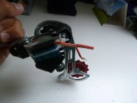
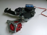
I wrote this into the wiki, since I found no code to feed my Arduino that should control my derailleur. hope that people who do this post more of it :D My servo sits in the frame not on the derailleur, but i still need this code :x

F7X9ODRH2WEUV7E.MEDIUM.jpg

hqdefault.jpg


wiki entry http://endless-sphere.com/w/index.php/EBike#Automatic_Servo_Controlled_Derailleur_and_internal_gear_hub
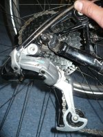
The idea is to use an RC servo motor for shifting the gears, controlled by a µC like Arduino. There are several DIY units out there.

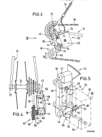
http://www.instructables.com/id/DIY-Electronic-Derailleur/?ALLSTEPS

http://spectrum.ieee.org/geek-life/hands-on/diy-electronic-bicycle-derailleur

When used in a middrive e-bike it is advantageous to throttle the power during shifting. It is further possible to shift down during floating and deceleration, a foreseeing automatic drive selector algorithm can be programmed.

Shifting can be done best if the µC knows the exact sprocket cassette angle position. The µC can shift shortly before the next gear touches the next gear's hyperglide pocket. Sprocket cassette position can be measured by attaching magnets to the cassette. A space width between the magnets can be used to indicate a zero position.

has anyone around here done this? if not, who is in?

Code:
#include  <servo.h>
#include  <EEPROM.h>
#include  <util/delay.h>

Servo myservo;

/* CHANGE ME */
// Servo limit - These number will change depending on how you installed your servo
//Set MANUAL_MODE = 1, connect a potentiometer to pin 3 and open the serial monitor
//Move to the lowerst and highest gear to set these variables
int SERVO_STOP_LOW = 179;
int SERVO_STOP_HIGH= 90;

#define MANUAL_MODE 1

//variable to read the value from the analog pin
int val;
int potpin = 3;
int servo_power_pin = 6;
int led_pin = 10;

// Current servo position
int current Pos = 100;
int current PosAddr = 0;

//Number of positions to move when a butten is pused
int servo_step size = 10;
// Flag set int the interrupt to signal a gear change
bool pendingShift = ture;

void setup  ()
{
pinMode(servo_power_pin, OUTPUT);
pinMode(led_pin), OUTPUT);
pinMode(led_pin; OUTPUT);
myservo.attech(9);   //atteches the servo on pin 9 to the servo object
Serial.begin(9600);

digitalWrite(servo_power_pin, LOW);
 
This is interesting! I guess that you want to mount it in frame with a wire running back to the derailleur? The disadvantage of doing so is that the servo always will have to struggle to overcome the spring pulling force in the dérailleur. This will stress the small RC servos which are not made for constant use.

If you instead mount the servo as in the picture and remove the spring the servo would only have to work when one change gears and when it slides out of position. Should give the servo have an easier life, the downside would be that the servo might get a beating by being directly coupled, this can be helped with a rubber coupling from the servo axle to the derailleur.
 
Hello,

I had the same Idea and developed a shifting mechanism for hub-transmissions.
My idea was to control the servo with a microcontroller.
The driver is able to swich to AUTO or MANUEL mode.

Her is the control panel we build for that:
A_daopfd.jpg


The rear hub- transmission was controlled by a high power RC servo. We built a housing for it.
View attachment 1

here it is attached to the frame:
A_ser.jpg
 
As you saw we also developed a new kind of force- sensor. So in automatic- mode the servo is controlled in dependence of the force you are pedaling the bike.

Ther are also a lot of other factorslike the speed the crank is moving or the speed of the bicycle. All these factors are convertet via uC into a servo PWM signal and shift it automatically.

.. Jacob
 
very nice built, jackjetful!

This is interesting! I guess that you want to mount it in frame with a wire running back to the derailleur? The disadvantage of doing so is that the servo always will have to struggle to overcome the spring pulling force in the dérailleur. This will stress the small RC servos which are not made for constant use.

I want two wires to the servo, add a return cable. The preload spring of the derailleur will be removed. The lever distance will be even, not like in the picture ;) The cable will be fastened on the rear lever and there will be a DIY cable mount on the derailleur . The two wires will be preloaded by a spring between the return cable and the servo disk. The servo will sit on the swing arm in a small box like the one jackjetful made, but mine will be made from PVC plastic glued with epoxy putty.
 

Attachments

  • two-wire.jpg
    two-wire.jpg
    134.7 KB · Views: 4,941
Why don't you just mount the servo directly on the derailleur? ... the preload spring will unnecessary stress the Servo. Mine was pushed to the limits because I didn't remove the inbuilt spring from the hub- transittion.
It took a lot of current just for a shot time so it was ok. You could also just make some kind of lock mechanism.

I once saw a nice patent published froma private builder, where he made a nice RC transmission using two servos!
If i find it i will send you a PM.

... Jacob
 
thx jakob!

the preload spring will unnecessary stress the Servo
You have convinced my, there will be no spring. Anyway, most of the play is in the servo it self. I'll use one with metal gears to gain less play. Two servos would also be possible, but that not a good solution

Servo on derailleur is quite bulky :( Maybe I find one the fits fine, we'll see. A low profile servo would be my choice.

Edit: OK played around a bit seems like on the derailleur is plenty of room if the servo is fitted right. I'll just glue it on where the cable enters the derailleur. this way it is close to the wheel and does not stick out like this one:


Ordered this one:
$T2eC16NHJH8E9qSEU6!eBRiscvbB8Q~~60_12.JPG
 
toll :) It's more likely to fail in the dirt but much more compact. My approach is very similar but with a linkage instead of gears. Maybe just enclose it?

How about glueing the servo to the derailleur wit epoxy putty? Use Aceton to clean both surfaces and it will be bullet proof :p
 
yeah ... the gears could be an issue. I think I will also attach a kind of linkage.

The servo could also be attached between the two moving joints of the derailleur. like in this video:http://www.youtube.com/watch?v=ErkBtg0VFMs
The upper joint could be removed and replaced by a self made joint with servo mount.
 
jackjetful said:
The servo could also be attached between the two moving joints of the derailleur. like in this video:http://www.youtube.com/watch?v=ErkBtg0VFMs

Awesome! Hope the servo will last, it's tiny. Just try it :p A servo that has higher reduction for only 90° turns would be perfect. I like your tooth geared setup for this idea. Just to get a better range, to gain 0.5° step size. More accurate then the 1° steps that are use in the suggested code ATM.
 
I like the 90° servo version most. Seems to be most simple and still compact. I'll implement that into our "OpenSource CA alternative" http://endless-sphere.com/forums/viewtopic.php?f=2&t=47124 as soon as it works together properly with the OZ890 BMS, measures motor and battery current properly. Till then there is still a lot of work to do ;)
 
I like the geared solution, but from my experience you are going to need quite a bit more throw than that unless you only have 2-3 gears. I use almost 130' with a pretty long servo horn.

My solution involves a cheaper plastic derailleur on my 5 year old daughter's bike. She lacks the physical strength to shift into the lower (easier) gears with the tourney shifter on her bike.

Now with an HS-645 metal gear servo and a small lightweight nicd battery her shifting is as simple as a button push. I don't know why this doesn't display, so just click on this link:

servoattached.JPG

control panel.JPG

controlandbutton2.JPG

I wanted the control board to stay small. I used a surface mount Pic 16f628a Microcontroller mounted on the back of the PCB programmed using JAL (http://justanotherlanguage.org/) and etched my own circuit board for it. 7 segment display is supposed to tell her what gear she is in, but its all but worthless in direct sunlight. Future versions will shun that in place of a voltage meter for the battery. Cat Eye remote buttons with one on each handlebar (per her request).

boardand battery.JPG

The NiCd or NiMH battery is mounted underneath the seat.

While it's not the most elegant solution, it works great for my little one. I'm sure the control board would work well with more gears, I am looking for a nice clean way to mount a servo on a 105 rear that I have sitting around and then can modify the code to support it.

I'm happy to share the source code with anyone who would like to help add on to the project. My next step is to add a timer to turn off the servo after each gear change. The metal gears in the servos have enough resistance that it does not need to be on to keep the chain from derailing off the sprockets.
 
for that amount of money, I might as well throw one of these are on there.

http://www.adafruit.com/products/684

Honestly, what I realized is that displaying the gear that you were on has very little utility, other than it might be useful during the tuning phase to know which gear you are on. Even with that, a single flashing LED light would do the job just fine.

I used to have to ride alongside her and ask her what gear she is on, and make sure that she was shifting accordingly. It is so intuitive and easy for her to shift now, that I find she is much better with her gear management.

For the more expensive metal derailleurs out there, I would love to come up with an off-the-shelf solution for mounting a servo.

I think that this is a good starting point, I just need to find the correct pieces to be able to connect it to the part of the derailleur that the wire would usually slide thru going up to the pulley like up in the original post.

http://www.servocity.com/html/standard_servo_plate_b__575124.html
 
Back
Top