Bafang ultra upgrade to 2500watt

tatawaki said:
Thanks again for all the help thus far. I've decided to stick with a 52v battery for now. I'm currently running 50amps through it. I've put just over 500km and full throttle all the time and seems stable. I want to run more power (maybe slowly work it up to 60amps). Do you think this the stock controller can handle it?
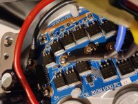
I've added thermal paste on the backside of the controller to help with heat dissipation

worst case: https://www.greenbikekit.com/accessories/bafang-8fun-spare-parts/ultra-g510-mid-motor-parts/bafang-ultra-510-controller-48v-30amp.html

EDIT: I'm at 54 AMPS and the initial test was fine (very cool outside) rode to work in +11c weather and seems ok. Bike feels better, but I think 3500watts is ideal (60amp) for the weight and size of this bike.
IMG_1500 (1).jpg

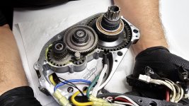
Caution, measuring external temps by hand feeling the aluminium diecast case is misleading. The motor stator is isolated to case by airgap most of the way around. So thermal transfer is minimal. Die-cast aluminium is poor heat conductor, comparing to extruded or forged aluminium part. I would say, if you measure temperature rise of 20c between air and case, then at least double that number to get motor stator temperature and triple that number to get wire temperatures as estimates.
Aluminium PCB with heat-transfer paste is wise ;)
:thumb:
 
barbarossa said:
Hi,

TVS diode is placed between voltage supply for controller and controller - using the display controller connection ( controller voltage feed - 5pin HIGO = green plug). I used a Bafang display cable extension from aliexpress and soldered the TVS diode in.

aliexpress.JPG

TVS diode is placed between brown cable (P+ power supply).
Wire.JPG

display_plug_brown.JPG

if you have 78 volts and put a 16 volts TVS diode between = 62 volts for the controller.

meanwhile I also use 100 volts caps (1000uF and 560uF) - a little more than specified by Bafang :lol: it is really funny: Bafang printed "100V..." on the controller board and in fact they use 63 volts caps.

Bafang1.JPG

Bafang2.JPG

but hey, caps are not really the problem.
85 volts mosfets means that you normally only should use 80% = around 70 volts. 78 volts is already borderline. even better would be 18s and charge up to 4.1 volts each cell group = 73.8 volts.

and I totally forgot: Anderson battery connectors should be replaced e.g. by XT60 (in case of using higher current).

cheers

Trying to figure out how to run my Innotrace controller on 17S.

Any idea if this would also work on the Innotrace controller?

Innotrace has a 59,5V high voltage cutoff, that they said can't be removed. The controller won't feed the motor if the voltage is above this.

Wondering if the TVS diode is put in, will the controller see less voltage and allow operation?

Also, the Innotrace has IRFS7530 fets which seem to be 60V max. I'm thinking about replacing them with IRFS7730 (seems similar but 75V max). I wonder if this would be a good move? Caps are 100V rated so shouldn't be a problem.
 
TVS on the display power line didn't work for Innotrace controller.

I'll try some other possibilities when I have time.
 
Hello guys.

Have a new CAN controller v.2

I wanna do shunt mod. But now 5 shunts 2mOhm. See picture. Could be there is one for each motor phase? There wasnt till now phase current sensing, am I right?

I doubt all 5 are for DC, that woyld be only 0.4mOhm

100V FETs used
 

Attachments

  • IMG_20211007_210636.jpg
    IMG_20211007_210636.jpg
    415.1 KB · Views: 800
Monte said:
TVS on the display power line didn't work for Innotrace controller.

I'll try some other possibilities when I have time.

247323110_10159712620145513_4935784491651673934_n.jpg
Here's where to put a TVS diode on Innotrace controller for higher voltage. I drilled through the trace on the PCB here.

Mine had IRFS7530 fets so for higher voltage these would have to be changed. Don't know if a newer revision of the controller uses different fets.

Anyway, I decided to place a Nucular on pre-order instead of changing out the fets on the Innotrace since Innotrace doesn't allow much user configuration.
 
Has anyone tried the TVS diode on the CAN ultra motors?

I tried on mine and it will not turn on the display. Any ideas?
 
Hi everyone. Stupid question: is 5mohm resistor the same as 0.005ohms? :)
Is 5mohms a five milliohms or megaohms? :)
 
5mOhm is 0,005 Ohm
5MOhm is 5 000 000 Ohm
 
Hi everyone. I soldered 1x5mOhm resistor and don't see any changes in displaying watts/don't feel any extra power. Looks like nothing happened :)
 
Hi everyone. I soldered 1x5mOhm resistor and don't see any changes in displaying watts/don't feel any extra power. Looks like nothing happened :)
To be clear the display with not show this change, do you have a photo of how you soldered it on? Do you have a bluetooth bms that can display the outgoing amps?
 
Unfortunately I don't have photo and bluetooth bms... :(
I soldered it in parallel to existing two, both of them simultaneously. As the original ones are in parallel, I think it os OK scheme?
May be I'm too heavy and don't feel the difference climbing to the hill.. :)
To be clear the display with not show this change, do you have a photo of how you soldered it on? Do you have a bluetooth bms that can display the outgoing amps?
 
In parallel with the original ones is correct. You won't see any difference on the Bafang display, but the actual amps pulled should be higher.
 
Unfortunately I don't have photo and bluetooth bms... :(
I soldered it in parallel to existing two, both of them simultaneously. As the original ones are in parallel, I think it os OK scheme?
May be I'm too heavy and don't feel the difference climbing to the hill.. :)
Should be good, If you soldered on the extra shunt right on top of the two the same way the originals were and soldered all three together should be working. How good is your battery can it handle the extra amps? To be honest I had a similar reaction to doing this with my bbshd, power didn't feel that big of an increase. Maybe I just got used to it but I expected a lot bigger of a difference. The only real way I could tell it was working (because I also thought maybe it wasn't) was the torque from a stop improved a lot, would wheelie from a stop unlike before and I also picked up about 4mph extra top speed on my lowest gear. Maybe see if you notice I difference like I did. From what I've heard though doing two shunts to 60A is where the difference really becomes noticeable, if your battery can spare it I would put another on top, you can always go back and limit the power through software if its too much. Also I just want to confirm you are running a UART controller correct?
 
Should be good, If you soldered on the extra shunt right on top of the two the same way the originals were and soldered all three together should be working. How good is your battery can it handle the extra amps? To be honest I had a similar reaction to doing this with my bbshd, power didn't feel that big of an increase. Maybe I just got used to it but I expected a lot bigger of a difference. The only real way I could tell it was working (because I also thought maybe it wasn't) was the torque from a stop improved a lot, would wheelie from a stop unlike before and I also picked up about 4mph extra top speed on my lowest gear. Maybe see if you notice I difference like I did. From what I've heard though doing two shunts to 60A is where the difference really becomes noticeable, if your battery can spare it I would put another on top, you can always go back and limit the power through software if its too much. Also I just want to confirm you are running a UART controller correct?
Yes, I'm running UART.
I'm 220 lbs+ 80+ lbs bike, and may be I'm just too heavy to feel the difference :)
Sometimes it feels like something changed, but it is hard to be sure :)
Today I tested the speed and it is 30mph maximum on a flat road. Display showed 1470w, so I belive it is real maximum for 40/11 teeth.
Current battery is custom and should provide 45a without any problems.

Anyway, thank you for your feedback!

I'm gonna make new battery in a month or two, and may be then try to add one more shunt. Will see :)
 
I managed to melt the plastic gear running stock power levels, so be advised that gear is a weak link. I don't know if there are metal or PEEK gears available for the Ultra.
 
I managed to melt the plastic gear running stock power levels, so be advised that gear is a weak link. I don't know if there are metal or PEEK gears available for the Ultra.
I believe the Ultra's swapped to all metal gears a few years ago, shouldn't be an issue
 
I managed to melt the plastic gear running stock power levels, so be advised that gear is a weak link. I don't know if there are metal or PEEK gears available for the Ultra.
I believe the Ultra's swapped to all metal gears a few years ago, shouldn't be an issue
Heh, my definitely has metal gears :)
 

Attachments

  • 20231214_182737.jpg
    20231214_182737.jpg
    2.7 MB · Views: 11
Hi everyone. Does anyone know resistance of temperature sensor in the motor, or even model number? Looks like I broke my one while disassembling :( Display shows error 10 - motor overheat :(
 
Is the actual sensor broken, or just the wires to it? (AFAICT from a quick google search, the sensor is in the stator windings so damaging the sensor itself would probably make the motor unusable).

If you can still get to the sensor leads you could probably reconnect the wires to it.

If not, you can try a 10k NTC thermistor, as those are the most common type used in this stuff.

There are many versions with various Beta numbers; if there's enough of the leads remaining to touch multimeter leads to you can test the resistance at a few different temperatures and use some math (look up "calculate beta of a thermistor") to get the beta you need to replace it with.

If you can't reach it, then you can try 3900, 3500, etc., and see if it appears to read correctly as it gets hotter--if it is way off then the beta is wrong, but if the system still works and you know you won't overheat it in your usage, that wont' matter.
Thank you!
I pitched the wire while maintenance (and I added one more 5mohm resistor). Cut damaged part of wire and soldered it, but error still persist.
Controller shows error code 10 (motor overheat) when sensor is connected, and error 11 (sensor fault) when sensor is disconnected. Thus I suppose that's something happened with sensor only (?)

Will try to check some sensors, thank you!)
 

Attachments

  • 20240121_163727.jpg
    20240121_163727.jpg
    1.2 MB · Views: 6
Since there's apparently no actual sensor damage (if sensor is not in that pinched section but is instead buried in the motor windings), then if fixing the pinched wire does not fix the problem, it probably means that whatever reads the sensor was damaged by whatever was shorted during the pinch.

The sensors themselves are hard to damage electrically if they're thermistors.

Three-wire sensors like LM35 or DSxxxx types (analog and digital respectively) can have their outputs damaged if they're shorted to something, but that looks like a two-wire sensor and those are almost always resistive.
Uh, I see. Thank you. So, do you think that replacement is a better option?
 
Back
Top