Hey all. Looking to build a badass battery to replace my current setup. I have the orientation of cells figured out but have questions about how to wire the pack. I'm not sure whether I'll hire somebody to build the pack or do it myself. If I can get enough information here I may just do it myself. Specific things I have questions about:
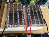
Wiring. This will be a 20s 10p pack. So do you wire 20 10p packs in series? Or 10 20s packs in parallel? It seems the first option would be the easiest because you can just take a chunk of 10 cells and bridge the connections on all of both sides. Then it's just a matter of wiring those in series. But in terms of electrical flow seems the second option might be better because with the first option you have more current flowing through some batteries with less reaching the end of the line. It seems with the second option all the cells would charge and discharge more evenly. I hope that makes sense. I'm not sure if this matters or not.
My other question is about sourcing a BMS. Would definitely like to find an American brand as opposed to finding something off Ali Baba. If I use tesla model 3 cells I'll need something that can do 150 amps. (72v)
I can answer those two questions I may just build the pack myself. If not I'll have to find somebody. Can anyone recommend somebody? I am near San Francisco.


