BifRC PCB spot welder - gate driver modification help & advice needed.

pegaz666

10 µW
Joined
Mar 4, 2024
Messages
6
Location
shimano666
Hello,
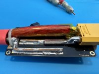
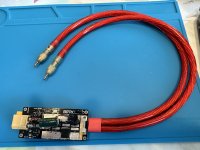
Hopefully someone can help me out here. I know these pcb spot welderers are junk but after beefing up all the traces, making my own AWG 4 cables and electrodes and using a separate power source (small 3s battery) just to power up the electronics while using originally 5s 4500mah 40C lipo (charged to storage= 19V) as a welding source (positive avoids going through the board and goes directly to welding tip while negative goes through the mosfets on PCB). It’s got 7 gears where each one of them represents a 10ms short increase. So 1=10ms, 2=20ms and so on. I had to use it on level 7=70ms.

It was doing quite well for a while - i’ve done 600shots through 0.1mm pure copper and 0.15mm pure nickel sandwich just fine. Although my lipo was getting hot and eventually died at around 400 shots (internal lipo tab burned off) i was able to remove the cell and convert this 5s lipo into 4s lipo but this time i had to use it fully charged at 16.8V or something.
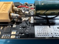
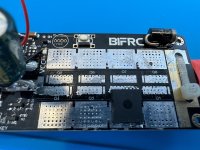
I keept continuing like that until it burned the inner tab again and fry all the mosfets + mosfet that was controlling all gates… I have bought an exact replacement mosfets IPLU300N04S4-R7 from china again (probably fake hence the failure?) as well as that little mosfet that controls gates. Since I couldn’t fix my battery again i have bought a brand new 4S 10.000mah 100c continuous (200C peak) CNHL lipo. I’ve charged it to storage and used it with my welder on level 3/4 now so 30-40ms. The welds were looking great, lipo was cold, i was making 30sec stops before each weld. Out of sudden after 25 shots it blew up again: new battery :( , all mosfets and mosfet for gates! I don’t know what happened and why this time it lasted so short??? Did mosfet fail and made all other mosfets to fail and longer than 70ms pulse broke the internal lipo tab again? Or it was the battery being too strong that triggered all of that disaster???

This time I don’t want to risk buying knock-off mosfets from China instead I will get them from Mouser:
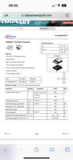
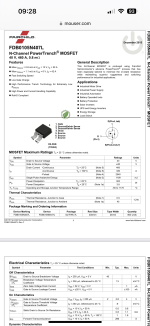
I was thinking about original replacement: IPLU300N04S4-R8 OR maybe instead it would be better to put the same ones used in kWeld: FDB0105N407L since they seem “stronger”?
Don’t know which ones I should go for - not a specIalist with all these parameters (both data-sheets attached).

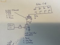
Since this time the cost of the components is significant I wanted to protect mosfet gates somehow (kWeld also got some zener diode and resistor near each mosfet). If one mosfet will fail and gate gets shorted at least it won’t kill all other mosfets. I believe this is what its for…

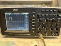
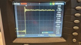
COULD SOMEONE PLEASE suggest what to put in line with each mosfet gate? I have drawn some diagram to show how it looks on my welder and attach some pictures from oscilloscope to show how pulses look like on this spot welder. Many tanks in advance!

@tatus1969 - maybe You could give me some advice how to stop blowing all mosfets at once? Thank you!
 

Attachments

  • 449B36B3-382C-4A57-998B-3CEDB6D9E430.jpeg
    449B36B3-382C-4A57-998B-3CEDB6D9E430.jpeg
    1.8 MB · Views: 10
  • EA958D38-5353-4429-8C1A-F3D10386635A.png
    EA958D38-5353-4429-8C1A-F3D10386635A.png
    1.6 MB · Views: 7
  • 318D0885-48B1-4BA7-B675-13A3EE866B12.png
    318D0885-48B1-4BA7-B675-13A3EE866B12.png
    807.6 KB · Views: 7
  • 2BA4973D-97E6-4CC1-9182-6F0BDAF8E20B.jpeg
    2BA4973D-97E6-4CC1-9182-6F0BDAF8E20B.jpeg
    2.3 MB · Views: 9
  • CD3BF110-FD98-46D1-87A3-E795DA2589A2.jpeg
    CD3BF110-FD98-46D1-87A3-E795DA2589A2.jpeg
    2.6 MB · Views: 8
  • 5AC55288-9C4A-4250-8A66-D68128A51D0B.jpeg
    5AC55288-9C4A-4250-8A66-D68128A51D0B.jpeg
    2 MB · Views: 8
  • 194A4111-A623-468D-80AF-08A376AA39D9.jpeg
    194A4111-A623-468D-80AF-08A376AA39D9.jpeg
    1.8 MB · Views: 6
  • BDE17C7D-284B-4048-A92F-1049999F2842.jpeg
    BDE17C7D-284B-4048-A92F-1049999F2842.jpeg
    2.7 MB · Views: 8
  • 6AF403FE-6991-465A-8E52-9525A948C712.jpeg
    6AF403FE-6991-465A-8E52-9525A948C712.jpeg
    771.9 KB · Views: 12
Last edited:
Don't know specifically what you need to change, but some thoughts:

Larger resistance in series with gate drive signals slow down the turn on by limiting gate charge current, leaving the FETs in the linear range longer, making more heat. It's probably not heat causing the initial failure of the FETs, so that's probably not a problem here.

FETs have a limit to the gate-source voltage; spikes above this can destroy the gate, this often turns the FET permanently fully on in the process, causing full current flow until the FET or something else in the current path fails and stops the current flow.

They also have a limit to the drain-source voltage; spikes above this can do the same thing. Spikes can be very very short, and may not be visible on a scope if it's not high enough bandwidth (fast enough input response), even if you expand the ringing / transition part of a signal to fill the screen horizontally. The scope trace doesn't show a very high voltage ringing, or a very low negative voltage (assuming the low level is ground reference), but I don't know how well that scope can show very short transients. (I also don't know what point on the circuit the scope pictures are showing signals for, or when in the process they are showing).

They also have a limit to the currents in each of these paths, and spikes above those limits can also destroy them, but since the current usually destroys by heating, they usually have to be much longer than the voltage spikes to do their damage, and are usually easier to spot.

Zeners can be used to prevent excess gate-source voltage spikes; as long as the zener is fast enough reacting it may protect a gate well enough. The voltage the zener activates at (see it's chart on it's spec sheet) should be high enough that the gate is fully turned on.

TVS can be used for drain-source spike mitigation, might work on the gates too if you find ones low enough in voltage for the purpose.

Capacitors with long legs from the PCB do their job less well, as there's more resistance between the current flow they are filtering and the capacitance doing the filtering, so it takes longer for the charge/discharge to happen, so more ripple in the current and voltage.

Lipo cells are often rated far higher than they are actually capable of, and in applications that use very high pulse currents from them they may be too high a resistance and far more heat than should be created for such a rating is made.

If the Lipo interconnect fails, the circuit opens, and any inductance in the path collapses it's current into a voltage spike, which if it's high enough across them, can destroy the FETs. The same is true if current is still flowing when the electrodes are pulled off the welded surface. The higher the current, and the higher the inductance, the higher the resulting voltage spikes.

If there is any arcing in the weld process (from a tiny gap between the electrodes and the surfaces, etc), the RF generated can cause problems in the FETs leading to damage or failure.


It's a little different technology, but you can also look at the high-power controller design threads and see how those FETs are protected.
 
I am assuredly no expert either, but I have chased rabbits a few times.

So, you blew up batteries 2 units, and repair bits from one of the units... so you have effectively blown up 3 of these.

Couple perspectives.

1) The definition of insanity is doing the same thing over and over and expecting different results.
2) That unit... yeah, there is no way that thing is gonna last. You have a size 2 circuit board and are trying to push size 9 power through it. Heat dissipation alone will get ya.
3) might want to find yourself a K-weld, from what I recall it is about $100 or so, granted I don't own one. I bought a vevor unit before I ever heard of the kweld, it was about 150 if memory serves, I don't regret it, I have thus far made it work. However I do know with hindsight I should have either gotten a kweld... Or honestly now that I have built my 50th pack... I should have bought a good machine. I just did not foresee this being my new big hobby...
 
Don't know specifically what you need to change, but some thoughts:

Larger resistance in series with gate drive signals slow down the turn on by limiting gate charge current, leaving the FETs in the linear range longer, making more heat. It's probably not heat causing the initial failure of the FETs, so that's probably not a problem here.

FETs have a limit to the gate-source voltage; spikes above this can destroy the gate, this often turns the FET permanently fully on in the process, causing full current flow until the FET or something else in the current path fails and stops the current flow.

They also have a limit to the drain-source voltage; spikes above this can do the same thing. Spikes can be very very short, and may not be visible on a scope if it's not high enough bandwidth (fast enough input response), even if you expand the ringing / transition part of a signal to fill the screen horizontally. The scope trace doesn't show a very high voltage ringing, or a very low negative voltage (assuming the low level is ground reference), but I don't know how well that scope can show very short transients. (I also don't know what point on the circuit the scope pictures are showing signals for, or when in the process they are showing).

They also have a limit to the currents in each of these paths, and spikes above those limits can also destroy them, but since the current usually destroys by heating, they usually have to be much longer than the voltage spikes to do their damage, and are usually easier to spot.

Zeners can be used to prevent excess gate-source voltage spikes; as long as the zener is fast enough reacting it may protect a gate well enough. The voltage the zener activates at (see it's chart on it's spec sheet) should be high enough that the gate is fully turned on.

TVS can be used for drain-source spike mitigation, might work on the gates too if you find ones low enough in voltage for the purpose.

Capacitors with long legs from the PCB do their job less well, as there's more resistance between the current flow they are filtering and the capacitance doing the filtering, so it takes longer for the charge/discharge to happen, so more ripple in the current and voltage.

Lipo cells are often rated far higher than they are actually capable of, and in applications that use very high pulse currents from them they may be too high a resistance and far more heat than should be created for such a rating is made.

If the Lipo interconnect fails, the circuit opens, and any inductance in the path collapses it's current into a voltage spike, which if it's high enough across them, can destroy the FETs. The same is true if current is still flowing when the electrodes are pulled off the welded surface. The higher the current, and the higher the inductance, the higher the resulting voltage spikes.

If there is any arcing in the weld process (from a tiny gap between the electrodes and the surfaces, etc), the RF generated can cause problems in the FETs leading to damage or failure.


It's a little different technology, but you can also look at the high-power controller design threads and see how those FETs are protected.
Many thanks for your detailed response - lots of good info in there. Since on one set of Chinese FETs (most likely also fake) it lasted for around 400 shots I'm hoping that if I go genuine it will last much longer. On top i will modify gates by adding 220Ohm resistor and Zener diode (18V) DDZ9705S since FETs gates are rated at +/-20V and I'm running 3s ~12v to power up electronics. On top I will add some TVS for drain-source spice protection. I hope that all of that will improve its reliability.

PS.
1. My scope was connected directly at the gate pad.
2. Since during last weld where everything blew up it burned a hole in the nickel strip that would suggest that FET was the first to fail and triggered all of that disaster and longer "closed" time burned lipo tab. If lipo burned first there wouldn't be any hole as it would cut the power (i think...).
3. Since i was doing breaks between shots like 30sec or so I've never had a problem with the heat. These mosfets weren't even warm that's why I've resigned from putting heatsinks or fan on them.

I'm still tempted to try and hope that the above modifications will improve this welder's operation. I wish I could afford 250eur for kweld...
Many thanks again!
 
I am assuredly no expert either, but I have chased rabbits a few times.

So, you blew up batteries 2 units, and repair bits from one of the units... so you have effectively blown up 3 of these.

Couple perspectives.

1) The definition of insanity is doing the same thing over and over and expecting different results.
2) That unit... yeah, there is no way that thing is gonna last. You have a size 2 circuit board and are trying to push size 9 power through it. Heat dissipation alone will get ya.
3) might want to find yourself a K-weld, from what I recall it is about $100 or so, granted I don't own one. I bought a vevor unit before I ever heard of the kweld, it was about 150 if memory serves, I don't regret it, I have thus far made it work. However I do know with hindsight I should have either gotten a kweld... Or honestly now that I have built my 50th pack... I should have bought a good machine. I just did not foresee this being my new big hobby...
I get your point but:
1. I have never used a mosfet bought from a reputable source: i got them from aliexpress for 20% price of a genuine unit so no, that's definitely something new to try and that could definitely be a different and significant change. It's not the first time chinese chip by part number promises to do something but its not doing that in real life (last time i’ve bought some voltage regulators IC rated to 60V by datasheet - both (one after another) of them blew within a second upon connecting to 56V, I got the same exact chip from Mouser and it works perfectly since a year now).
2. Since i was doing breaks between shots like 30sec or so I've never had a problem with the heat. These mosfets weren't even warm that's why I've resigned from putting heatsinks or fan on them.
3. I wish i could afford kWeld - find me one (even second hand) for 100$ and i will scoop out the money. They are (with electrodes and taxes) 250 EUR shipped - that's too much for my hobby use (mind that not everybody earns in USD, EUR or GBP).
Regards
 
Last edited:
I get your point but:
1. I have never used a mosfet bought from a reputable source: i got them from aliexpress for 20% price of a genuine unit so no, that's definitely something new to try and that could definitely be a different and significant change. It's not the first time chinese chip by part number promises to do something but its not doing that in real life (last time i’ve bought some voltage regulators IC rated to 60V by datasheet - both (one after another) of them blew within a second upon connecting to 56V, I got the same exact chip from Mouser and it works perfectly since a year now).
He says to the proud owner of half a pallet of "gen u ine" LG cels, that registered one and all at 1800mah which was decidedly not what I bought.

They made terrible 12v units, but I give those away, and I got a refund the shipment, I guess the only real loser was my poor suffering wife (the only parking slot under cover here is hers.. in the garage with me... it gets uhm.. borrowed a lot)
2. Since i was doing breaks between shots like 30sec or so I've never had a problem with the heat. These mosfets weren't even warm that's why I've resigned from putting heatsinks or fan on them.
Yeah, I guess that would help. I hear patience is a virtue.. ::grins::
3. I wish i could afford kWeld - find me one (even second hand) for 100$ and i will scoop out the money. They are (with electrodes and taxes) 250 EUR shipped - that's too much for my hobby use (mind that not everybody earns in USD, EUR or GBP).
Regards
I went and looked. Stuck my foot right in it there. Bit pricey that. I don't think I have ever seen one used, I know the local maker group was hitting people up to get one for the group. I tossed in a few bucks and rumour has it that they bought one. You should check your local makers group.. never know.
 
I dont know, my colleague is using something similar and is quite happy with that (but not this exact type), but anyway this is an example, different shops make different types of devices - you'd need to ask about specific materials and capabilities (the one i linked, it says there that you could even weld 1mm plates with long enough time and good clamp -but i cant confirm that)

But i'd say this is more solid than a battery-based chinese board - first of all, it's on AC transformer so it's not a consumable power supply like a battery, and has got a triac-based switching which should be more immune to burning out than mosfets. Better quality wires and electrodes - it all adds up, i thing one decent device should be cheaper in the long run..
 
Back
Top