BionX 48V battery not responding but cells are ok

Hello Evryboy,
I did buy a 2nd hand bionX powered ebike with 2 CAN batteries :
- The first battery : the bms/controller board is dead and flash red while the li-ion pack is ok :(.
- The 2nd batteyr : charges the pack only to 3.8v each elementwwhich give 60% of the pack capacity :(.

I am not far from office so i lived with this "half charge" for a couple of years but as the pack is getting tired my autonomy is getting very low.

I was glad to read this thread and will proceed as my french camarad, ie. remove the bionx board from my battery and put inside :
- 55v to 12 v buck converter
- 12v to 5v regulator
- 13s 40A BMS

I wasn't sure of the current capability and the power that the 2 voltage regulators would have to handle so i did built a small test board to mesure the current sinked by the bionX systeme.

In case it would help anybody i wanted to share these numbers here :
- on 12v seems that around 300mA are sinked
- on 5v seems that 10 mA are sinked.

Also is seems to work good with 5v as well as 5.5v.

basically one could use :
- 1 HV DC/DC switching converter module to step down 55v to 12v with a "good" efficiency (look for LM2576HV at your favorite chinese vendor)
- 1 small linear (or switched) regulator to step down 12v to 5.5 or 5v to save some volume inside the battery case.

Other point, a cheap module like the LM2576HV usualy sinks 10 mA continuously on the battery pack (you can start by removing the led to save a couple of mA). Saying taht i would recommend (as my franch camarad) to insert a waterproof switch on your battery to prevent it to get discharged during long time OFF periods.

Last point, the picture displaying the pin out of the battery conenctor is wrong is this thread.
IT is like this

\ 0A o2 o1 0B /
\ o5 o4 o3 /

OA = BAT =
OB = GND
o1 = 5.5v = red wire
o2 = CanH = green wire
o3 = wake up = black wire
o4 = vctrl 12v = brown wire
o5 = CANL = white wire

Thanks again to all contributors that helped me reviving my batteries.
 
Anyone alive in this forum?

I changed original Bionix BMS to chinese one, I added 12V and 5V stepdown converters:

OA = BAT = ->DONE
OB = GND ->DONE
o1 = 5.5v = red wire ->DONE
o2 = CanH = green wire -
o3 = wake up = black wire
o4 = vctrl 12v = brown wire ->DONE
o5 = CANL = white wire

But the system doesn't wake up.. Do I miss something? I tried to add 200 and 400 resistor on green + white - no chnages.
Do I need to use black (wake up) wire somehow?
 
ALN, I'm about two weeks behind you, apparently. Did you get your battery to wake up? If so, please let me know what you did. I'm installing my new BMS tonight and the voltage converters later this week. Fingers crossed!
 
For anyone who trips across this dead thread in the future, I repeated what Auber38 (June 16, 2020) did up above. It worked perfectly! I have function back, except no regen braking and no battery monitor. The controller seems a bit slower to respond than it did before, but I have a functioning system again!
 
crustulu said:
Some updates from my side.

My 48v CanBus system with dead BMS works like a charm. I use it everyday.

For now i just removed the BionX BMS, installed a standard 13s Chinese BMS with balancing function, added 2 DC/DC converter one for +5V and one for +12V. I also added a opto-magnetic 30A relay operated by the +5V and a simple rocker switch on the outside of the battery. When the switch is off, the DC/DC converters are disconnected and the relay is in idle position witch means that the + of the battery is connected to the charge plug. When the switch is on the DC/DC converters are on, the relay is activated and the + of the battery is connected to the socket. Do not plug a battery in the bike with tension on the socket, it will produce a huge spark.

The CanH and CanL wires are shorted with a 240 Ohm resistor for the moment.

The console and the motor can communicate without the battery original BMS, the only things that lacks are the battery gauge, the regeneration and the odometer that acts very strangely. No automatic shut-down after 10 minutes like it was said above.

On the CanBus Hack side, for now i just listened to the communications of the system on my wife's bike witch is fully functional. I think that i have discovered the codes for battery voltage, state of charge, regen on/off. The problem is that the Arduino doesn't fit inside the battery rigth now, i have to reprocesses the overall wiring for that. I will continue that later i think.

Cheers,

Alexandre.

Hi Alexandre,

I have read with great hope your posts concerning reviving a Bionx without the BMS. I have a system with a dead battery and have opened the battery case and tried to use it with an external battery (having its own internal BMS) connected to the internal battery wires. As it was a 39,6V system (based on the existing cells) and I only had a 48V battery, I didn't dare to use it full but discharged it to around 45V which left me with around 20% capacity. To my surprise, the system woke up with a series of chirps and then it worked until my battery died. Then it didn't want to wake up anymore.

So I decided to try your method and repeated all steps as per your post, unfortunately without result. The only unclear thing was about the CANh and CANl wires. Did you short them to the ground through a 240 ohm resistor? Or did you just put a 240 ohm between them? Or something different?

I have connected the battery directly to the motor, 12V to the motor and 5V to the console (I have a small basic Ride+ console on a Diamant bike) and Ch and Cl are connected between the console and the motor (plus the 240 ohm resistor). The screen is on but I cannot change the assist level and seem to have no consumption on the motor (wattmeter).
Any advice will be highly appreciated. Kind regards,
Dan
 
wdeutsch said:
For anyone who trips across this dead thread in the future, I repeated what Auber38 (June 16, 2020) did up above. It worked perfectly! I have function back, except no regen braking and no battery monitor. The controller seems a bit slower to respond than it did before, but I have a functioning system again!

Hi Auber38 and wdeutsch,

How did you do it? Please see my post above with what I did. I seem to be stuck in the same situation as ALN above, not knowing what to do with the Ch, Cl and wake wires.

I am getting crazy about this now. Thank you for any advice,

Dan
 
Hi,

I am currently doing this conversion for a friend with a busted bionx Battery, I will keep you in touch if it works.
 
Hi again,

Here the picture of the bike and my test battery, for the moment the display goes on but the motor does not start.

Any ideas?

bionx1.jpgbionx2.jpg
 
How do you check the diagnostics?

found it:

https://electricbikereview.com/forums/threads/how-to-get-access-to-your-bionx-console-code-menu-codelist-included.519/

I have G2 console
 
Ok it works!!!!

I wasn't pushing enough on the pedals to start the motor.

Fun Fact, the lights do not work or is there a light sensor that holds the lights from shining even if turned on?

Diagnostic Mode gives Error 00 30 26 which is normal:

>> 26 = No communication between Console and Battery: Check connections and focus on those between console and battery.
 
iacei said:
Fun Fact, the lights do not work or is there a light sensor that holds the lights from shining even if turned on?
Is it wired directly to the battery?
 
I think it is wired to the battery via a special pin that gives current only when console sends the signal but as there is no communication anymore between the console and the Battery it does not work anymore.

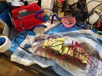
Here a pic of my ongoing Battery replacement

IMG_20210505_201624.jpg

It will have an extra switch on it and the new charging socket will replace the old one.
 
wdeutsch said:
For anyone who trips across this dead thread in the future, I repeated what Auber38 (June 16, 2020) did up above. It worked perfectly! I have function back, except no regen braking and no battery monitor. The controller seems a bit slower to respond than it did before, but I have a functioning system again!

Hi,

I have the same problem with the slow response. Thanks for any help.

I have done the same thing, with the mention that I have 36V system with a Ride+ display, the simplest one, on a Diamant Ubari+ bike. I have completely eliminated the battery and its connectors and soldered the wires directly. I have added a 120ohm resistor between CANh and CANl where I joined the wires (tried also 240, other resistances).

The system works, but it is extremely slow to respond to the commands from the console (display). I can increase/decrease the assistance but only as follows:
1. I keep the + button pressed for 30 seconds (min 30, max 60) and release it
2. After I release the + button, I have to wait for 25 seconds (precisely!) for the command (bar) to be taken and appear on the screen
3. Then I can repeat the process

If the bike is still for more than 10 minutes, the assistance goes back to zero.

It is very cumbersome but at least it works! However it is not usable if you want to change the assistance on-the-go.

Any ideas on how to solve that? Thanks again!
 
Back
Top