BLDC controller, highly advanced.

I ditched the fast and expencive ir2110s. Intersil is sending me someHIP4086A 3-phase drivers for testing. These are 4 dollars each. With some nice protection circuitry built into it Working out the resistor, diodes and capacitor costs for this part of the circuit. Missing some pull-down resistors and some zener-gate protectors - will add them soon. Just posting this schematic before I mess it up with these missing things :lol:

View attachment elkontroll.pdf

Some mouser links for parts i'll use.
G-S zeners, smd
shottky-diodes, smd
22uf electrolytic, 16v
0.1uf ceramic smd
Another shottky 1A diode
Low esr 10uf 16V electrolyte
 
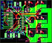
Fitted everything to a 45x35mm board! Traces are not done yet - nearly everything is connected. Left to do is sizing capacitors for smoothing ripple.

elkort.png

I'll connect all the top drains electrically and thermally, DC+ connects here. All the lower fets will have each own heatsink witch also serves as phase A, B and C connection.

Final multisim schematic is this total mess xD
View attachment elkontrol2l.pdf
 
What is acceptable bus ripple voltage in a ebike-controller? Is 1V acceptable in a 74V system? What kind of phase inductance does a big hubbie show? 40 uH, 50uH?

Ofc ripple isn't our biggest concern, inductive spikes is. I'm looking at using film capacitors, so reducing needed capacitance to a minimum is of great essence.

As of now, it looks like I can use 150uf worth of high grade film capacitors to smooth the voltage. Or even less: allowing 3% voltage ripple(2,2V), 50uH load, 50% duty cycle; 50uF is enough! :shock:
 
Teh Stork said:
What is acceptable bus ripple voltage in a ebike-controller? Is 1V acceptable in a 74V system? What kind of phase inductance does a big hubbie show? 40 uH, 50uH?

Ofc ripple isn't our biggest concern, inductive spikes is. I'm looking at using film capacitors, so reducing needed capacitance to a minimum is of great essence.

As of now, it looks like I can use 150uf worth of high grade film capacitors to smooth the voltage...
I think the ripple is ok as long as its below the limits of your components. But if you see 1v that doesn't mean that under some parameter you didn't test there isn't 10v ripple. I'm going to try to ease up on the voltage as I scope my power stage and then load test it all on the dyno to look at as many different scenarios as possible.
 
Arlo1 said:
Teh Stork said:
What is acceptable bus ripple voltage in a ebike-controller? Is 1V acceptable in a 74V system? What kind of phase inductance does a big hubbie show? 40 uH, 50uH?

Ofc ripple isn't our biggest concern, inductive spikes is. I'm looking at using film capacitors, so reducing needed capacitance to a minimum is of great essence.

As of now, it looks like I can use 150uf worth of high grade film capacitors to smooth the voltage...
I think the ripple is ok as long as its below the limits of your components. But if you see 1v that doesn't mean that under some parameter you didn't test there isn't 10v ripple. I'm going to try to ease up on the voltage as I scope my power stage and then load test it all on the dyno to look at as many different scenarios as possible.

Well, I've designed the powerstage pretty solid from what I've read from application notes. 10uf lowESR + ceramic for the bootstrap( x3). 22uf electrolyte+0.1 ceramic is used to decouple the uC. Double schottky diodes are used to further protect against inductive spikes in the gate circuitry.

I'm tempted to drop the 18V zener + 10k gate-source resistor. Dropping these and adding some more "near mosfet" SMD capacitors seems like a better use of the space. And shorting the lower gate circuitry by 10mm isn't nothing either :p
 
Teh Stork said:
As of now, it looks like I can use 150uf worth of high grade film capacitors to smooth the voltage. Or even less: allowing 3% voltage ripple(2,2V), 50uH load, 50% duty cycle; 50uF is enough!

That's all well and good... except for the minor point that motor inductance has minimal-to-zero effect on the ripple voltage/current. The inductance of the battery path and the inductances associated with the FET packages, leads, and traces are what you need to be concerned about.
 
rhitee05 said:
Teh Stork said:
As of now, it looks like I can use 150uf worth of high grade film capacitors to smooth the voltage. Or even less: allowing 3% voltage ripple(2,2V), 50uH load, 50% duty cycle; 50uF is enough!

That's all well and good... except for the minor point that motor inductance has minimal-to-zero effect on the ripple voltage/current. The inductance of the battery path and the inductances associated with the FET packages, leads, and traces are what you need to be concerned about.

Well, film capacitors have very low inductance and very low resistance. Motor inductance have everything to say for the inductance of the battery pack. Low voltage ripple = battery inductance path dealt with.

Why do I say inductance and not ESR? Well, ESR have many measuring modes, often measured at 1kHz. Our useage, at 20kHz, makes such ratings useless if the inductive portion of the ESR (at 1kHz) is high).

What you are talking about, stray inductance, is best dealt with by other methods.
1. Keeping motor leads together, making the magnetic field collapse into themselves instead of through the mosfets.
2. The mosfets WILL be subjected to repeated pulses (avalanche rating (mosfet working as a diode)). Mosfets need to be sized to handle these! I'm not parallelling fets - since I know the extreme measures needed to protect these. Single fets aren't as hard :)
3. Smart driver features: shoot through protection, turn on delay, turn off delay - you name it.
4. Fall time. Fall time. Fall time. Fall time. SO much depend on this and wheter stray inductance gets the better of you. If stray inductance (x resistance =voltage) beats diode recovery: buh-bye mosfet :roll:

Capacitors offer some protection, but are no solution to stray inductance :|

Some good reads:
- Film bus capacitors: from Epicaps


And why this confusion?
This document posted long ago. We don't have any freewheeling mosfets in our 3-phase inverters!

Sorry if I'm coming on to strong here, but there is too much confusion around this shit xD I do have questions on most areas, but stray inductance: I've done my research :wink:

I'm planning on making this power stage physically small, so that I can put it very near the axle with little problem.
 
The energy in a 500nF inductor, charged to 100A, is 2,5mJ. (0,5*L*I^2) (most mosfets are avalanche rated at 200-2k mJ)

A small capacitor inbetween phase wires can reduce this pulse some.
A capacitor (2uf) charged (e=0,5*C*V^2) to 75V contains 4,9mJ. If the capacitor absorbs the whole inductive spike, the voltage on it after the spike is 86V (turn the equation).

How low ESR/ESL is needed for the capacitor to absorb the energy? quite frankly, I don't know how to measure this. As a start, this is the theory behind induced voltage:
Given 100ns fall time: induced voltage (given linear fall) is ((V=L(di/dt)) L=500nF, di=100A, dt=100ns. ) in the order of 2000V :eek: In reality, so many factors are to be included this will be different.


Then again, if the diode recovery time is less than the fall time - it should block the pulse. I'll add 2uf to my board now :)

The tinyed bit is bullshit, the inductive spike would lower the final voltage of the capacitor?
 
I've done some more layouting - its so tiny xD I'm not sure this is realizable, but it would be fun to try :p It should fit 8)

Layout.jpg

The board is 42x35mm. To put it in perspective - your bank card is twice the size of this board.
 
Look, I don't want to come on too strong here and you're welcome to do whatever you want... but you might try doing a little more reading because most of what you've been saying is pretty far wrong. Even if you insist on ignoring everything I have to say hopefully I can at least put up a flag for other newbies to ignore this thread until you learn what you're talking about. No offense intended

Teh Stork said:
Motor inductance have everything to say for the inductance of the battery pack. Low voltage ripple = battery inductance path dealt with.

This doesn't make any sense. Motor inductance and battery inductance have NOTHING to do with each other. Are you trying to say that if I switch to a different motor without changing anything else the inductance between the battery and controller will be different? You also have the cause and effect backwards - battery inductance causes voltage ripple.

Teh Stork said:
Why do I say inductance and not ESR? Well, ESR have many measuring modes, often measured at 1kHz. Our useage, at 20kHz, makes such ratings useless if the inductive portion of the ESR (at 1kHz) is high).

ESR is completely separate from inductance - that's what ESL is for.

Teh Stork said:
What you are talking about, stray inductance, is best dealt with by other methods.
1. Keeping motor leads together, making the magnetic field collapse into themselves instead of through the mosfets.

Keeping the motor leads close together will reduce their inductance, but a relatively small contribution compared to the inductance of the motor itself. And unimportant.

Teh Stork said:
2. The mosfets WILL be subjected to repeated pulses (avalanche rating (mosfet working as a diode)). Mosfets need to be sized to handle these!

The MOSFETs will not be subjected to avalanche unless you're doing something really, really, horribly wrong. The voltage ripple and/or spikes which will be seen in a controller are NOT avalanche.

Teh Stork said:
I'm not parallelling fets - since I know the extreme measures needed to protect these. Single fets aren't as hard :)

MOSFETs parallel very well and this is done very, very often.

Teh Stork said:
3. Smart driver features: shoot through protection, turn on delay, turn off delay - you name it.

These features have nothing really much to do with stray inductance.

Teh Stork said:
stray inductance (x resistance =voltage)

????

Teh Stork said:
We don't have any freewheeling mosfets in our 3-phase inverters!

Huh?

Teh Stork said:
A small capacitor inbetween phase wires can reduce this pulse some.

All a capacitor between phases is going to do is dissipate energy in the ESR.
 
rhitee05 said:
Look, I don't want to come on too strong here and you're welcome to do whatever you want... but you might try doing a little more reading because most of what you've been saying is pretty far wrong. Even if you insist on ignoring everything I have to say hopefully I can at least put up a flag for other newbies to ignore this thread until you learn what you're talking about. No offense intended

Teh Stork said:
Motor inductance have everything to say for the inductance of the battery pack. Low voltage ripple = battery inductance path dealt with.

This doesn't make any sense. Motor inductance and battery inductance have NOTHING to do with each other. Are you trying to say that if I switch to a different motor without changing anything else the inductance between the battery and controller will be different? You also have the cause and effect backwards - battery inductance causes voltage ripple.

Sorry, the bolded part does not make any sense. Neither does "except for the minor point that motor inductance has minimal-to-zero effect on the ripple voltage/current.". I was trying to respond to that, but failed. Blue part: no, I'm not saying that. Red part: Absolutely not. Current ripple (created by PWM!) CAUSES voltage ripple. The capacitor smooths the voltage from the battery. The voltage ripple is greatest at 50% pwm. ΔV0.5t = Vbus / (32 ∗ L∗ C ∗ f^2 ) can be used to predict the voltage ripple. Choosing a low inductance capacitor here is of great importance.

rhitee05 said:
Teh Stork said:
Why do I say inductance and not ESR? Well, ESR have many measuring modes, often measured at 1kHz. Our useage, at 20kHz, makes such ratings useless if the inductive portion of the ESR (at 1kHz) is high).

ESR is completely separate from inductance - that's what ESL is for.

ESL is often factored in in these ESR measurements, so you need to be careful while choosing capacitors. Was just trying to point out going for a low ESR cap might be a bad choice.

rhitee05 said:
Teh Stork said:
What you are talking about, stray inductance, is best dealt with by other methods.
1. Keeping motor leads together, making the magnetic field collapse into themselves instead of through the mosfets.

Keeping the motor leads close together will reduce their inductance, but a relatively small contribution compared to the inductance of the motor itself. And unimportant.

No, you've got this totally wrong. Motor inductance is stored in materials with magnetic properties, this is like syrup compared to the magnetic field around the phase wires! The inductance from the phase wires will make a inductive spike once the mosfet turns off - and the mosfet will need to block/clamp it. To say it in other words: the time constant of the phase wire inductors is significantly less than of the motor stator.

rhitee05 said:
Teh Stork said:
2. The mosfets WILL be subjected to repeated pulses (avalanche rating (mosfet working as a diode)). Mosfets need to be sized to handle these!

The MOSFETs will not be subjected to avalanche unless you're doing something really, really, horribly wrong. The voltage ripple and/or spikes which will be seen in a controller are NOT avalanche.

Firstly, I want to correct myself. The mosfet is working as a zener diode - not a diode. The mosfet will be clamping spikes every now and then, (i might have gotten this wrong -->), the avalanche rating is there to say how big this pulse can be before normal operation (the mosfet can start conducting f.ex) is disturbed.

rhitee05 said:
Teh Stork said:
I'm not parallelling fets - since I know the extreme measures needed to protect these. Single fets aren't as hard :)

MOSFETs parallel very well and this is done very, very often.

They are, but for a hobbyist going for single fets is easier. I hope to be able to parallell whole power boards in the future - as this board only have mosfet driver and mosfets. Current sense will have it's own board, and uC will have its own.

rhitee05 said:
Teh Stork said:
3. Smart driver features: shoot through protection, turn on delay, turn off delay - you name it.

These features have nothing really much to do with stray inductance.

I agree. But then again, you can tie stray inductance to nearly everything.

rhitee05 said:
Teh Stork said:
stray inductance (x resistance =voltage)

????

Just wanted to add the whole sentence for context.
"4. Fall time. Fall time. Fall time. Fall time. SO much depend on this and wheter stray inductance gets the better of you. If stray inductance (x resistance =voltage) beats diode recovery: buh-bye mosfet"

Yeah, I agree that the bolded part is wrong. Should say something like: if Voltage/fall time exceeds diode recovery - problems occur. And that induced voltage = inductance*change of current/fall time. Just want to point out that motor inductance is neglitiable and phase wire inductance is the dangerous one here.

rhitee05 said:
Teh Stork said:
We don't have any freewheeling mosfets in our 3-phase inverters!

Huh?

Well, we're supposed to switch to the next phase in our bridge. And I was referring to the info in that document.

rhitee05 said:
Teh Stork said:
A small capacitor inbetween phase wires can reduce this pulse some.

All a capacitor between phases is going to do is dissipate energy in the ESR.

No, it will reduce some of the inductive spike from the phase wires. When the cap is charged - no current is flowing, and none is lost to ESR.

Sorry for my previous post containing these mistakes, you were right to raise the "newb flag". Then again, many of your points are flawed too - i hope the further discussion won't be too colored from this.
 
I'm not here to argue, I have better things to do. Best of luck.
 
I need to lay down some goals for my project.

Goal: build a robust - powerful and cheap controller capable of operating a HS3540. 7500W burst. 18s (66v nominal).
Driver: HIP4086. A bit sloppy on the rise time side, but with nice features. I'm concidering going for 12 smaller fets (with one driver each) instead of 6 huge ones.
To do:
1. Add multisim footprint of AT32UC3B0256-A2UT.
2. Draw multisim schematic of inputs and the likes of the controller stage. Design it with breakout pins for later addition of features. (Lights, horn, you name it). Draw in ultiboard.
3. Calculate capacitance needed, setup simulation in multisim with battery-motor and general resistance calculated in.
4. Calculate heating in gate resistor.
5. Find the appropriate Mosfets. Decide 6 or 12.
6. Voltage regulators.
7. Produce controller board.
8. Produce driver board.
9. Program controller to drive easy six-step hall-based commutation.
10. Add current sense.
11. Get it to run.
12. Flirt with FOC and synchronous mode.
13. Communication with android.

I'm learning a lot, and writing to the wiki would probably be a nice way to rub it in - but as of this date the wiki does not accept white signs - so I can't log in.
 
Teh Stork. I'm not here to stir the pot, but rhitee05 is a very well educated fellow. I would listen to his advise. I know some of the examples he give you are correct. But im not up to his speed yet! I wish you luck with your controller. Unfortunately as I have already experienced you do need a certain number of things RIGHT to make a controller work. For the power levels you are looking at and the motor you want to drive a lyen 18 or 24 fet would be far far cheaper and in all honestly probably give you the same performance!
 
Arlo1 said:
Teh Stork. I'm not here to stir the pot, but rhitee05 is a very well educated fellow. I would listen to his advise. I know some of the examples he give you are correct. But im not up to his speed yet! I wish you luck with your controller. Unfortunately as I have already experienced you do need a certain number of things RIGHT to make a controller work. For the power levels you are looking at and the motor you want to drive a lyen 18 or 24 fet would be far far cheaper and in all honestly probably give you the same performance!

Rhiite05 is definitely well educated. I was "blinded" by the documents I read, being supplied from line rectified. Here current ripple peak is at 50% duty cycle. Taking battery inductance, resistance and the likes proves to be a very challenging equation. Being backed up by my electronic teacher did definitely add to the cockyness, but I see now that his knowledge in this field is limited - as he was quite blank on what to do to model such a system in multisim.

Many of the threads here on ES contains the best info avatible on how to look at this, I havent had the time to fully take everything in yet - but rhitee05 is the author of much info on this topic.

I already have a 12 fet clyte controller - will mod it to around 70A 66V nominal. Will definitely be a fun ride :) I'm looking to learn as I find electric motors and systems very interesting :) Learning through creating, and failing - has allways been a hobby :p

I find MLCC's interesting. Beats tantalum caps at high freq, cheaper and low inductance in a smd fixture. Low ESR (Even tho I cant find any numbers for it) is often advertised. One I know said MLCC's practically have zero ESR - and that the only thing I had to be careful of was operating temperature. Tried measuring ESR with my ESR meter, it was out of range. Same meter Doctorbass uses, measures my big electrolytes down to 10mOhm - but doesn't give a reading on some tiiiny 1206 mlcc's. But i can't seem to find anyone using ceramics. This one from mouser certainly seems appealing..

One, of my many, side project I have is building a vacuum induction heater for casting titanium :p I allways have 3-4 projects going, and I keep learning more from these than school will ever teach me :)

Made a simple simulation of gate resistor today - seems like 0201, or more fittingly a 0402 will do the job just fine ;) Will post schematic later, need to know if there are other sources of heating.
 
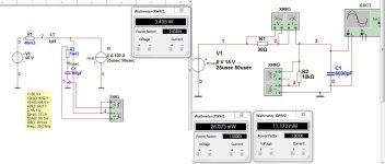
Here is some of what I've been looking at for the controller.

These can be used in multisim to simulate different stuff.

First one, an attempt on looking at capacitance needed. The second one is an attempt at looking at dissipated heat in resistors. I want to minimize resistor footprint, to further reduce inductance and PCB size. Looks like I can use 0402 for both gate and gate-source resistor. (Theoretically a 0201 can handle 50mW, but soldering these are really hard.)

Here are a random snapshot of both calculations. I realize the squarewave current is a bit off, but this gives me a ballpark figure. How much time will I spend on 50% duty cycle - that is also a question..
multisimm.jpg

Here are the sim-files: View attachment calcs.rar

Edit: Using triangular current source - the voltage ripple is drastically lower. In the order of 30A instead of 60A. Trying to get a exponential current source to work - but this won't cooperate with me xD
 
A word of extreme caution about simulations. SPICE is a great tool, extremely useful, but it is only a tool. Simulation results are only as good as the model used to generate them. In other words - garbage in, garbage out.

Constructing a valid model is hard. In fact, constructing a model and understanding the conditions under which it will be valid is pretty much the main problem in engineering. A resistor is not just a resistor. Under some conditions, the appropriate model for a physical resistor may be 4 or 5 elements. The same goes for other components, and that's why making a model is hard. Worse, an approximate model may not generate an approximate result - it can sometimes be wildly wrong. Knowing all of this is the difficult part of engineering. SPICE will quite happily give you an answer for any model you give it, it's up to you to create the model and interpret the results.
 
You're saying something there rhitee05. Tried modeling the whole battery inductance + resistance, mosfets, decoupling capacitors, motor inductance and resistance into one circuit - that didn't go as planned. Trying to simplify things and take one step at a time. In my model for decoupling capacitor, the motor is simplified as a pulsed current source. Still can't get the exponential current source to work - this will make the ripple somewhat smaller.

Was thinking about having adjustable PWM for the areas near half duty cycle. If I double the frequency, the ripple is more than halved in my simulations. (From 12.2V p-p to 4.5V p-p).

Is using ceramics for the whole brunt of capacitance (150-300uf) a viable way? The very low ESR and low inductance is tempting :)
 
Yep, there are lies, damn lies, and simulations. I learned a long time ago to not bother doing them... one prototype is worth 1000 simulations.
 
I'm really lost in this sizing the decoupling capacitor stuff.

Can the motor really be calculated out of the question?

Since I do not have any data for the HS3540, here is a 5303 xlyte. I do not know how this sizes up to the HS3540, but this is to have a time-constant to calculate after.

From the wiki: "
inductance between two phase wires: 0.169mH
DC resistance between two phase wires:0.097ohm"

This gives a time constant of some 1750 uSec. Or some 35 20kHz pwm cycles before the motor is fully "charged". The time constant affects how fast the motor will get to current limited by resistance. (I=U/R). In the case of the 5303 at 66v. This is 680A. Using multisim I created this transient analysis to 130A.

View attachment .pdf

This does not show the full 1750uS, but only the start. It shows that it will take about 8 full pwm cycles to reach desired phase amps.

As you also can see from the graph, the current is also nearly linear.

I do mean that this is important for capacitor sizing, but how do I calculate it in?

Thinking out loud here, hoping someone can help :)
 
The powerstage and motor can simply be simulated as a pulsed current when playing with capacitor values. It doesn't matter if the motor current has some slope to it.

The ceramic/film capacitors are only there to take care of the flanks. They need to have low ESL. The electrolytics take care of the main current. To be able to simulate what's going on during the flanks you need to model: the electrolytics ESL+ESR, stray inductance between the electrolytics and the ceramic/film, and stray inductance between ceramics and power stage.

Regarding your cocksure answers to rhitee05 earlier, I would like to know on what science you are basing your answers? to me it seems like rhitee05 has got it all right, which makes you the one who needs to explain your sources and reasoning.
 
bearing said:
The powerstage and motor can simply be simulated as a pulsed current when playing with capacitor values. It doesn't matter if the motor current has some slope to it.

The ceramic/film capacitors are only there to take care of the flanks. They need to have low ESL. The electrolytics take care of the main current. To be able to simulate what's going on during the flanks you need to model: the electrolytics ESL+ESR, stray inductance between the electrolytics and the ceramic/film, and stray inductance between ceramics and power stage.

That makes sense :) I was thinking about dropping electrolytics entirely, but it looks like there is no way around them w/o spending lots of money :p

bearing said:
Regarding your cocksure answers to rhitee05 earlier, I would like to know on what science you are basing your answers? to me it seems like rhitee05 has got it all right, which makes you the one who needs to explain your sources and reasoning.

This document:Selecting Film Bus Link Capacitors
For High Performance Inverter Applications

Why won't it link :S - Selecting Film Bus Link Capacitors
For High Performance Inverter Applications: from Ecicaps
 
Teh Stork said:
This document:Selecting Film Bus Link Capacitors
For High Performance Inverter Applications

Why won't it link :S - Selecting Film Bus Link Capacitors
For High Performance Inverter Applications: from Epicaps

That article is fatally flawed and very, very wrong. Their entire analysis is based on the assumption that somehow the input current is equal to the output current, which is not at all correct. There are several other errors - or at least unstated assumptions - but that initial assumption makes the entire article worth exactly nothing. I could write quite extensively and explain exactly why that's wrong and how you actually need to do it, but I have a feeling that would be a waste of my time. I would suggest you start with some very basic reading on these topics - there are lots of good app notes and such available online, and anything related to buck converters is applicable to BLDC controllers as well (3-phase buck, basically). You're going to find yourself very far over your head very quickly (if not already) unless you get a better grasp of the basic theory at work here.
 
Maybe you should start here:
http://endless-sphere.com/forums/viewtopic.php?f=30&t=31804
Rhitee, you should check my last post on this thread. (and the attached file). I'm no master, but I really think it can be used to our purpose (you used to say the opposite a few months ago, i'd like you to check again please, and get your advice).

That article is fatally flawed and very, very wrong.
You''r right, everything isn't good on internet.

Motor inductance still doesn't matter for capacitor sizing...
I'm not 100% sure about that after all. Ripple curent in DC capacitors is linked to Modulation index, which seems somehow liked to motor inductance and resistance (has to be confirmed).
Point n°2: DC capacitor ripple current isn't proportional to Irms (of the system) <= If someone has a bench to test it, I'd love it to be confirmed (I'll have my homemade controller to test this soon)

one prototype is worth 1000 simulations
Depends on your needs.

Have a nice day
 
Back
Top