BLDC Motor Controller (High torque, low RPM)

sesj13

1 µW
Joined
Jul 29, 2013
Messages
4
Hello all,

I am currently designing a BLDC motor. I need the outrunning rotor to rotate at around 100rpm (although the exact speed is not crucial). So far I have designed and manufactured the stator and rotor, as shown here:

BLDC_zpsf04ff687.png


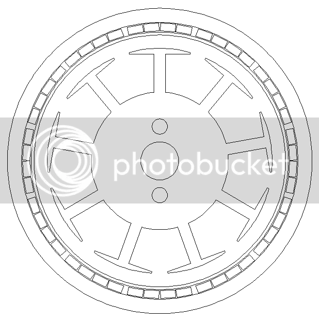
The outer radius of the stator is 30mm and the inner radius of the rotor is 33mm - these are the maximum and minimum dimensions that can be achieved, so there is a large gap between them (~3mm).

From reading about online, I believe that to control a BLDC at low RPM I would need to utilise hall effect sensors to sense the true rotational speed of the rotor? I have looked into sensorless controllers but they look like they're designed for a high RPM, low-torque turn on (like RC planes). I believe I have found a suitable controller here:

http://www.oem.co.uk/Archive/FilesArchive/229263_1_812.pdf

I am just wondering if anyone has any experience/thoughts on this, it would be much appreciated. If you need any more details just ask. :)
 
The motor looks quite similar to other BLDC. Do you want to share some more details like type of magnet, iron sheet thickness, number of turns in the winding :)
About low speed control it does seem rotor detection with Hall sensors works best. The controller you posted as far as I saw has at least two limits: max 36V and max 8Amps. The voltage is less critical if you can compensate thru current, but that's even more limited. What kind of power / torque are you looking for?

cheers
 
Thank you for your reply. I used two sheets of soft iron, each of thickness 3.3mm - so a total thickness of just under 7mm. From what I have read, stators are usually manufactured with laminated silicon steel to reduce eddy currents induced at high frequencies. This is very much a prototype I am designing, and hope that the soft iron will suffice. I have purchased 6x4x2mm 45H neodymium magnets. Each pole will be made up using 4 magnets (as can be seen in my diagram). I have wound the stator as: ABCABCABC using 26awg copper enammelled wire with each arm receiving 110 turns. I am not looking for very much torque at all - just to have the stator turning would be a start.
 
Hi sharris,

Is this just for fun or do you have an application in mind?

As your nominal funamental frequency is only 10Hz, I guess that even your 3.3mm thick laminations will be ok....
 
Hey Miles,

Yeah, I thought that - since the switching frequency will be so low, I won't need to worry too much about the material. I initially purchased a Mystery 30A ESC, but they are sensorless - which are useless for low rpm.

Does anyone have any experience controlling brushless motors at a low RPM?
 
I take what I said back, I don't think my motor provides enough back EMF for the Mystery sensorless ESC to work.
 
It may produce. BEMF is created by a combination of speed and magnet strength and grows linear with the number of turns for a given design. If the 110 turns are all series turns (and not say 5 series with 22 parallel threads per slot), you compare that to the 5-9 turns of the known hub motors... it's 10-20x more. Even if the airgap is more important and/or the iron is moer saturated you should still have quite a bit of EMF.
That said, about the 3.3mm iron; losses don't come only because of the 10Hz fundamental, but also because of the PWM switching @16kHz (usually). That said it shouldn't be a problem because a 110 turn motor should be quite inductive and filter HF.
 
drebikes said:
That said, about the 3.3mm iron; losses don't come only because of the 10Hz fundamental, but also because of the PWM switching @16kHz (usually).
I didn't think the PWM frequency had any direct bearing on parasitic losses in the motor?
 
On the motors I'm working on they have a huge impact, but they are higher power and speed (say 100x on both). By proxy I imagine you'd have some current harmonics on the AC side going in the motor which would create some eddy. The effect is usually small in the iron due to lamination, low in copper as it's more sensitive to RMS than frequency and quite high in the rotor (which may not matter as much for an outer-rotor motor as the hub rotor is easy to cool being on the outside).
If I were to do some syms (and I will when I have some time) the iron losses on a 3.3mm thick block from a say 0.5mm are supposedly rising with the square of the thickness, so (3.3/0.5)^2, 40x. If you multiply zero losses by 40 it's still zero, but you're bound to have some eddy at least in the end-turn region due to the non-parallel electric field lanes. I'm just guesstimating, should check. So in theory is should matter, but if we're just multiplying zero losses then it's ok.

P.S. I'm trying to modify KF's sym of the 9C 2809 hub motor, but I'm not very good with FEMM. That could be used to check things, but it may just be faster to try on a real motor and put a thermal probe to see how it goes :)

*EDIT: math
 
Miles said:
Did you see this thread, dr?
http://endless-sphere.com/forums/viewtopic.php?f=30&t=46210

I hadn't, 10x I was thinking I could post a quick reply after going thru it, but I have some reading to do.

As far as I've seen @work, PWM does create losses and increasing PWM frequency can have any effect depending on the system, it can increase or decrease motor losses (though it always increases controller losses as 2x faster commutations which means more grid energy being needed to switch the mos/igbt). It's a problem knowing what type of command the controllers send and I'm not to familiar with what ebikes do. If it's a trapezoidal quasi-brushed DC approximation, it is not likely the motor is going to benefit from increased switching frequency; if it's real PWM 2-level inverter then it might. It depends on the damping of the inductive circuit in the motor how much ripple current you have; more ripple (amplitude or frequency) gives more losses. On a thing I'm working now more frequency goes hand in hand with lower current THD; the result is for higher frequency PWM stator losses diminish (eddy and hyst), but in the rotor they increase - for a bike hub motor I'd always pick this higher PWM as I can cool the outer rotor better.

/back to reading

*Edit: This is not bad either:
http://www.endless-sphere.com/forums/viewtopic.php?f=30&t=29852&start=300#p678350
 
Sorry OP, hope I'm not hijacking the thread too much. I find I'm learning a lot on hub motor design and since I'm more the design type I'm happy to follow the actual construction of a part and the testing. The linked thread is quite interesting as it shows a bench and test results.

I'd only like to say I'm hoping on the ebike project I'm working to be able to do some very in depth testing if the components. One one hand I want to do a proper FEA model of the motor to estimate and then measure losses on a home trainer; there is a tool on the SKF site to estimate mechanical losses in bearings, it worked well for me 'till now http://webtools3.skf.com/BearingCalc/ I'm also curious on the command strategies being used and how they could be improved, I have a friend that knows some things on FOC command and given the time we could try to replace the driver stage of the controller with an AC PMW DSP.
Anyway, in my not-so-long experience with electric motors it's very hard to predict motor loss, especially at high frequency; rising PWM can give anything and everything with AC PWM (FOC). The thumb rule is more frequency is better for the motor because we command voltage, but the motor receives current; higher PWM allows for more granularity in voltage which gives closer-to-sinus current; but high frequency also traverses better parasitic capacitors, so not good.
 
Back
Top