Blown Controller

Harold in CR

100 kW
Joined
Feb 1, 2010
Messages
1,662
Location
Costa Rica
I have one that was blown up in CR. :roll: NOT by me. :lol:

I received it as a "possible" repair job, so I can get more hands on experience.

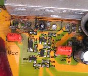
The 3 fets in the photo all have legs missing. I have new fets. Problem is, those microscopic parts that were singed when the fireball erupted. :shock: Some look like parts might be blown-burned off. IF I was to source these, is it possible to replace them, or, are they surface mounted ? The back side of the board has no sign of them, just the main traces being heavily built up with solder.
Lyenblowup.jpg

I KNOW I made that photo big enough to see the damage

I have done some searching using the forum search feature and Google search, using E-S in the beginning of the search criteria. Have found nothing showing any of this area.

Probably not cost effective to ship to Lyen, get repaired, maybe, and shipped back, so, what's all y'all's opinions :?

I'm game to try if it MIGHT yield good results. Just don't know nothing about this stuff. :?
 
it looks to me like it is your fet driver that you are looking at ...
if after replacing the fet your controller wonmt light up just try mirroring the other drivers for the other sets of fets
serfice moun dosnt men non repairable it just meens harder to repair
this being said i have read how fragile the driver circuits can be for litle things such as length of path/resistace/paracitic capasitance the list gose on

myself i would see if the "damage" to that driver was purely cosmtic from the fets bursting into flames beside them... msbee use a smal amount of rubbing alcohol on a q tip and clean the area up first and if no real damage is seen try replacing alllllllll the fets making sure they are properly matched
 
Thanks. When the photo was bigger, in Photoshop, I could see damage on a couple of those tiny pieces. One seems to be missing the whole upper section, the bigger one seems to be missing one corner. I tried to get a good close photo, but, the site made it fit their specs. Had to use a Magnifying Glass to see the damage.

I will try the alcohol thing. I used a dry rag, then moistened it with water, before the photo shoot.
 
We are looking at infineon 18fet controller? Have the same one dead on my table right now. And guess what - same fets.
I may have a theory why these three. Thing is, that controller threats this phase as a default one, when invalid hall signal is received. I mean, it will toggle these three fets when there is a malfunction in hall sensor cable or when it is disconnected at all.
Mine was blown during light, but slow acceleration at near-zero speed. It did spin fine before.
 
Yup, Infineon 18 Fets. You gonna try to repair it ? Is this an inherent problem ? The damage is on the power IN end of the fet bar.
 
first take out the three mosfets by cutting off the legs and save the insulating bushing on the screw. then some scouring powder on a toothbrush to remove the scorch marks and rinse and dry and then take close up of the traces from the mosfets over to the surface mount resistors.

do you have a voltmeter, power for the controller?
 
No worries about cutting the legs on those fets. They are GONE. :shock: :lol:

Yes, I have about 4 voltmeters and 72V battery pack to test with.

I will have to cut the epoxy holding the caps in place, then, remove the fets. Will do that this afternoon.
 
Have photos of the board with all 9 legs removed from the traces. The holes are somewhat filled with solder, but, I will clean them with a micro drill bit, by hand, when needed.

2 traces are loose from their original positions, but, I can deal with that. One trace, middle leg of 1st fet on the left has blown the tip of the trace away. I believe I can handle that, also.

Standing by for further assistance, which is GREATLY appreciated. Just would be nice to have a needle tipped iron, rather than a 80-120W Weller Pistol iron. :shock: :lol: :lol:
 
Harold in CR said:
I have one that was blown up in CR. :roll: NOT by me. :lol:

No one blew it up. It sizzle-popped without having ever spun a wheel. It happened on the first small pulse of the throttle to check the wiring combination. Send it to Lyen if you can't figure it out. He was notified back then and he said send it back. I'm just not willing to do the paper work to get it returned tax free, and no way I'm spending 2 way shipping and another set of import duty on something that was supposedly tested before shipment. My guess is a loose strand of wire or solder in the controller causing a short, because the same thing happened on a 24fet as part of the same shipment, except that one sizzled on power up, before having a chance to twist the throttle.
 
Chill out, John. :lol: I'm TRYING to figure it out. I even have some help offered. 8)
 
I'm always chilled. People just take what I type the wrong way. If I'm not chilled then I'm pretty clear about it. :mrgreen:
 
Yeah, mine is from LYEN, too. These are pretty crappy controllers. I did some investigation, redraw schematics of the mosfet driver circuitry... And it is really crappy:
DSC_0467.jpg

Upper fet has a 10nF cap on gate, and the gate is charged via 120Ω resistor. Switching losses must be huge. So here's why the fets blow up at low pulse width... Looks like I'll need a proper mosfet driver.
 
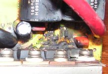
I will clean it all, before I get to do any testing of components. This shows the damaged parts on the board. Thanks.
 
Well, 2 of those traces are still good. Just not fastened to the board. In the photo, they are the left most leg of the 1st 2 fets. All 3 middle legs, I believe I can make work. High school SAT & manual dexterity tests, I was told to be a surgeon. No one ever told me how to finance that. :roll:

dnmun, IF I can do satisfactory repair to the traces, are you still game to talk me through testing those other (driver) parts ?

I believe that is where the problem will show up. The Q2A is the one with the side missing. The C2A might be completely blown away. ?

I'm too old to try to learn electronics, but, actual doing, I can take notes to be used later on by me and also anyone else that might be trying to learn this stuff by doing, not schooling. Tomorrow, I turn 69. :roll:

Maybe circuit will come up with an alt driver. He's not impressed with these boards at all. :lol:
 
the only thing you could test is to put the hall sensor plug on a wheel, attach the throttle, disconnect the phase wires, power up the controller, turn on the throttle and slowly move the wheel to see if the gate has a voltage that switches with the halls.

you cannot repair the gate traces. too much is gone and no way to reach in there with the soldering iron. shoulda used a soldersucker and less heat imo.
 
Most of that stuff was blasted away from the fets blowing. Thanks anyway. Onward and upward. :lol:
 
So I've fixed my "LYEN edition" controller. What I did is below.

tKo3d.jpg


Nope, there are not three, but four additional chips. Original mosfet drivers were driven via 120Ω resistor, which is madness. So I upgraded it a bit to 3A sink/source drivers. Also, original discrete low side drivers had an inverted signal, so I needed another hex inverter chip.

It spins well now (crystalyte x5). However here is what I've noticed:
SK2cc.png


This is unrelated to previous problems.
Channel 1 shows phase voltage at 100% throttle, channel 2 shows signal from one hall sensor.
What we see here is a 16 degree delay in hall sensor signal. Whoa! I'm not going to use THAT!
And the darn thing is unadjustable.

EDIT: when spinning in reverse, there is a 16 degree advance. Which is better (than delay), because it compensates motor's inductance at high RPM. But I can't mount my rear motor in reverse?!
 
it just looks so bad on the gate trace i don't see how it can be repaired. i guess you could leave the gate leg bent and sticking out so it would contact the trace that remains so there is some way to solder it down. not sure what the source and drain connections look like on the back which is where the solder sucker woulda been so useful.

but what you would wanna do is establish that there is voltage on the output of that diode D1A when the motor is being driven by the controller. so you have to have the hall sensors turning on the phase, and the throttle has to be on in order for the pwm to send voltage out to the gate and if you can find that voltage on the gate, then it would be worth trying.

i just cannot do that kinda small work anymore because my hands shake too much now. i can't even solder down the little 804 surface mount resistors. plus the ceramic cap is in the way and the phase wire and charge pump cap would block getting a soldering iron in there. all jmho. YMMV.
 
YUP, bending the legs out and hooking a wire to them was one idea. I have ran jumper wires to replace burned traces, on other projects, when that was a noticeable cure.

According to what Circuit has shown, looks like it would be a futile attempt to use the controller, once it was repaired.

Seeing as how I know as much about electronics as I do piloting the space shuttle, I have to do a bunch of studying, to see if I can figure out circuits-"circuit". :lol:

Thanks to both of you for trying to guide me.
 
well if you wanna, go ahead and check to see if the transistors will push charge onto the gate and if that little pnp transistor will still take it off. then remove the ceramic cap that is in the way and the charge pump cap too if you need to in order to work there under the mosfets.
 
Yeah, I'm too damn tired to even look at it, right now. Been chopping tall grass and weeds with a Machete. Gotta get the Kollmorgen powered weedwhacker halls thing figured out. Probably need to change them out, but, that 5 meg soldering iron is just a tad too big to get those tiny leads changed over. :roll: :lol: :lol: The magnet ring came unglued, but, I think it was getting loose when I bought it. If it weren't so difficult and slow to get a 80-100 motor shipped in, I would put that on the weedwhacker.

I've not given up on the infineon. Tomorrow is another day. Finally got my first round of charge-discharge done on 138 26650 cells. Need to check V on them all after sitting for 24 hours, group them up, and do some more charge-discharge cycles, so I can build up my 4 23S3P packs. Should have more by the end of next week to do. :roll:

I really just need to donate myself to a clone clinic and get reproduced, but, I need an electronics brain in the clone. :roll: :roll: :lol:
 
Back
Top