"Blue" NYC Ride-Share ebike

gfj902

1 µW
Joined
Jul 26, 2022
Messages
2
Top Down
I've acquired an existing Ebike. I'm looking for some help/insight in trouble shooting 1. Understanding the current system. 2. Adapting this system to a new bike using the current motor and battery, and thus how to charge and test the system.

Background
I was given this "NYC ride-share bike" that was found trashed. I don't have any more info than that. The motor and battery seem good. I have NOT tested anything yet. Furthermore, I dismantled the entire bike and separated the harness, controller, small module, battery (battery goes into a dock that mounts to bottle cage) and the wheel with a hub motor.

Here’s what I know:

Components:
- Hub Motor: Bafang 8Fun 250
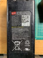
- Battery: SCUD (Model LF3614) 36V (468Wh/12880 mAh)
- Controller
- Small Module
- Torque sensor in the BB (Bafang)

Using the photo of the harness below, here’s what I think I understand:
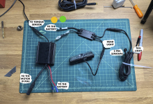
Screen Shot 2022-07-26 at 1.04.18 PM.png

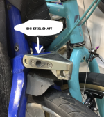
1. The bikes charges by being pushed into the street dock with a piece we’ll call the "Steel Shaft"
2. From the looks of it. There is a 2 pin clip (marked unknown in the photo) that is shared with the tail light. It connects to the Steel Shaft (I think..) and goes to the small module.
3. Out of the small module, there’s also a headlight, and two (yellow and green wired) white clips.
4. One of the white clips goes to the controller.
5. The other white clip goes to the battery.
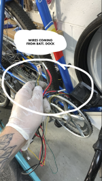
6. The bottle cage dock that the battery plugs into, currently has (4) wires coming from it. (2) x thick gauge black + red wires, and (2) thin green and yellow wires that go to the clip coming out the small module.

What I suspect is happening

- Because of these yellow and green wires… I’m lead to believe that small module is a communication module.
It connects to the battery and the controller, which ends on the Steel Shaft. When the steel shaft is plugged in, the communication module tells the system (cloud) that the bike is charging and where it’s charging.
- Another reason I believe this is a comm module is because the lights are tied to it. If the bike is moved… the lights flash.

What I want to figure out

1. Does this small module tell the battery when to discharge and charge, how can I test?
2. Can I run this system simply by by-passing this small module.
3. How can I charge this battery if the bottle cage doc has no input. It goes straight to the controller (Along with those little green/yellow wires)

My next steps would be:

- With spending as little money as possible, use the current system.
- Get a new controller (36/48V 22A), pas sensor, and display.
- I’m going to get a KT display and controller from Ebay since they are cheap and talk with each other.
- don’t foresee any issues with the controller recognizing the motor pug is the same. a common higo z9 or 910..

ANY INSIGHT WOULD BE APPRECIATED!

Other photos for reference
Screen Shot 2022-07-26 at 1.38.03 PM.png
294413876_1235507207200744_657447674440336289_n.jpg
295557733_384156417157764_2181331294231474150_n.jpg
Screen Shot 2022-07-26 at 1.39.40 PM.png
 
If it's a paid-rideshare type of system, then it won't operate without talking to the rideshare app (on your phone, usually) that tells it you've paid to ride it. Eliminating that requires finding and bypassing whatever communications unit is in the system, as that will "turn off" the controller, or disable it in some other way, until it receives the "ok" signal from the app that you've paid to ride it.

That could be in the 4-way "adapter" unit, or it could be in the battery's BMS, or it could be inside the actual controller.

To determine if the controller can be operated separately at all, you'd want to first check if the battery is outputting a full-charge (or non-empty, at least) voltage for it's particular number of series cells, while it is plugged into the controller (to provide a minimal load), while *not* being plugged into anything else, and with nothing else plugged into the controller except the battery.and the motor and the "torque sensor".

---If there's no output from the battery at that point, disconnect from the controller, and if it still has no output, your first task is to disassemble the battery to find out if it's because of a cell problem (protecting you from a fire, etc), or because it's just empty and needs charging, or because it's output is shut off by the rideshare system being non-activated. First task is to measure every cell group at the wires that go to the BMS, one pair of wires at a time starting with the battery main thick negative and the first thin small wire to the BMS, with a voltmeter set to 200VDC, and list every voltage you get here in this thread, starting from the most negative pair all the way to the most positive, which ends with the last thin wire to the main thick positive wire. (the first and last will probably read 0V, which is normal; everything in between should read higher than 3.5v, usually, and no more than 4.2v, if it's typical lithium ion). For 36v, It'l be a 10s battery, meaning 10 cell sets in series, so yo ushould have 10 nearly identical voltages between the two 0V readings.

---If there is normal output from the battery to the controller at that point, then try pedalling to activate the torque sensor (it may have to be mounted on a bike with some load on the rear wheel to make this work, like applying the brakes lightly if it is on a test bench). If it does not make the motor spin, then unplug the torque sensor and measure the voltages on each pin of the controller side of that connector with a voltmeter.

Voltmeter on 200VDC, black lead to battery negative, red lead to each TS connector pin in turn. You should read 0V on one pin (it's ground), then probably 0V on another pin (depends how it works), then 5v (or more) on a third pin (it's power supply). If it has more than three pins, there may be other voltages present as well. If there is no 5V+ on any pin, *but* there *is* correct battery voltage present at the battery positive connector, then the controller is either inactive (turned off) or damaged.

Move the red voltmeter lead to the first of the two pins of the controller wire going to that four-connector flat module (the module should still be disconnected). If it is a simple "KSI (keyswitch ignition)" input then there will be battery voltage on one wire, and 0V on the other wire. If so, you can then open up the controller and trace the 0V wire back to the solder pad on the board to verify it goes to the input area of the low-voltage power supply. (if you don't know what that would be, just post a good clear picture of the board, with an arrow showing where the wires from that connector end up on the board). If it does, then you would just short the two wires together to turn the controller on.

If the wires do not read battery voltage, but instead something like 2.5v or 5v, then it is likely to require communication with the 4-connector module to operate and may not be usable without it. More experimentation can be done if you like, before replacing the controller, because if anything goes wrong you would just replace it with a standard one, which would be the next step anyway. ;)


Something else to keep in mind is that if this rideshare service is still active / in business, then this bike and all it's parts is probably still their property, and could be listed as stolen, so posessing any part of it could get you in trouble, regardless of how it came to you. If you haven't already ascertained the legal state of the bike and parts, you may wish to do so before going any further. ;)
 
For charging the battery....first we would need to find out what the connections to it's internal BMS are. This requires opening it up to see, since there are multiple blade connections to the dock from it, and multiple wires out of the dock.

--- If it only has two wires coming out of the battery/BMS to the casing connector, then it's a simple one-port (common charge/discharge) BMS, and you just charge it thru the same connector it plugs into the controller with. (assuming there is no app-controlled board inside it that controls whether it can charge or discharge, and it's just a "dumb" BMS). In this case you just need a charger that outputs 42v at whatever the charge rate of that battery is, 5A max according to the label in the pic. (slower charge will be easier on the cells which gives them a longer lifespan, just takes longer to charge)

---If it has more than two wires, we'd need to know where those go inside the battery case to know which ones are used for what purpose, and whether it is a standard BMS or not, allowing normal typical charge, or if it requires something special such as communication with the system to work at all. If it does, then you might have to change out the BMS for a typical one to be able to use the battery.


Regarding battery specs, it's odd that they state the charge rate but not the discharge rate; if you get a new controller you would be best to ensure it does not use more currrent than the existing one to be sure the pack can handle it. If the controller has no label, then a guesstimate would be 250W (motor rating) / 36v (nominal battery voltage) = 7A.
 
If you want to use the lights, you'd need to know what voltage they run on, to be able to supply that to them. If you can measure the voltage at the module's light connectors when they are lit up (if they'll do that long enough to measure), that will tell you. Otherwise you may have to guess, testing with an adjustable power supply starting at 5v and going up until they light up normally. They could operate on battery voltage, but if you just hook them up to that and they can't handle it, they'll probably be damaged or destroyed.
 
amberwolf said:
If it's a paid-rideshare type of system, then it won't operate without talking to the rideshare app (on your phone, usually) that tells it you've paid to ride it. Eliminating that requires finding and bypassing whatever communications unit is in the system, as that will "turn off" the controller, or disable it in some other way, until it receives the "ok" signal from the app that you've paid to ride it.

That could be in the 4-way "adapter" unit, or it could be in the battery's BMS, or it could be inside the actual controller.

To determine if the controller can be operated separately at all, you'd want to first check if the battery is outputting a full-charge (or non-empty, at least) voltage for it's particular number of series cells, while it is plugged into the controller (to provide a minimal load), while *not* being plugged into anything else, and with nothing else plugged into the controller except the battery.and the motor and the "torque sensor".

---If there's no output from the battery at that point, disconnect from the controller, and if it still has no output, your first task is to disassemble the battery to find out if it's because of a cell problem (protecting you from a fire, etc), or because it's just empty and needs charging, or because it's output is shut off by the rideshare system being non-activated. First task is to measure every cell group at the wires that go to the BMS, one pair of wires at a time starting with the battery main thick negative and the first thin small wire to the BMS, with a voltmeter set to 200VDC, and list every voltage you get here in this thread, starting from the most negative pair all the way to the most positive, which ends with the last thin wire to the main thick positive wire. (the first and last will probably read 0V, which is normal; everything in between should read higher than 3.5v, usually, and no more than 4.2v, if it's typical lithium ion). For 36v, It'l be a 10s battery, meaning 10 cell sets in series, so yo ushould have 10 nearly identical voltages between the two 0V readings.

---If there is normal output from the battery to the controller at that point, then try pedalling to activate the torque sensor (it may have to be mounted on a bike with some load on the rear wheel to make this work, like applying the brakes lightly if it is on a test bench). If it does not make the motor spin, then unplug the torque sensor and measure the voltages on each pin of the controller side of that connector with a voltmeter.

Voltmeter on 200VDC, black lead to battery negative, red lead to each TS connector pin in turn. You should read 0V on one pin (it's ground), then probably 0V on another pin (depends how it works), then 5v (or more) on a third pin (it's power supply). If it has more than three pins, there may be other voltages present as well. If there is no 5V+ on any pin, *but* there *is* correct battery voltage present at the battery positive connector, then the controller is either inactive (turned off) or damaged.

Move the red voltmeter lead to the first of the two pins of the controller wire going to that four-connector flat module (the module should still be disconnected). If it is a simple "KSI (keyswitch ignition)" input then there will be battery voltage on one wire, and 0V on the other wire. If so, you can then open up the controller and trace the 0V wire back to the solder pad on the board to verify it goes to the input area of the low-voltage power supply. (if you don't know what that would be, just post a good clear picture of the board, with an arrow showing where the wires from that connector end up on the board). If it does, then you would just short the two wires together to turn the controller on.

If the wires do not read battery voltage, but instead something like 2.5v or 5v, then it is likely to require communication with the 4-connector module to operate and may not be usable without it. More experimentation can be done if you like, before replacing the controller, because if anything goes wrong you would just replace it with a standard one, which would be the next step anyway. ;)


Something else to keep in mind is that if this rideshare service is still active / in business, then this bike and all it's parts is probably still their property, and could be listed as stolen, so posessing any part of it could get you in trouble, regardless of how it came to you. If you haven't already ascertained the legal state of the bike and parts, you may wish to do so before going any further. ;)


WOW. I am so grateful for this incredibly intelligent and thoughtful post! I am going to print this out and bring to the garage with me on the weekend when I have time to look at this. The legality issues alone is asking me to abandon this project and spread the parts out in different garbage cans, like they do on the Sopranos.

I will start with the battery test using the voltmeter. Unfortunately, there was a casualty with the BB when removing it. The wires got severed at the plug so I won't have a torque sensor to test.

I have a suspicion that the little module helps the controller to tell the BMS INSIDE the battery to turn on... I mean, why else would there be separate wires coming out/going into the battery? I'll confirm and report back with some photos

Thank you again!
 
gfj902 said:
I will start with the battery test using the voltmeter. Unfortunately, there was a casualty with the BB when removing it. The wires got severed at the plug so I won't have a torque sensor to test.
I don't see a throttle, so if you don't have the pedal control then you can't operate the controller. (if it didn't come with a throttle, it's highly unlikely that you can add one)

Since you don't have any info (and may not be able to get any) on what exactly that sensor does and how it outputs what specific signal to the controller for what specific input from the rider, it's not all that likely you can replace the sensor. There are quite a few different torque sensor systems that each have their own power supply requirements and output methods, voltages, etc. If it has markings from it's manufacturer you have a chance of getting a new one, but...

So short of a new one, then to make the system usable at all, you'll need to peel back the plug insulation and cable insulation enough to see the wire colors, then test which wires go to which pins, so that you can reconnect them later or bypass the plug entirely and wire it directly into the cable from the controller.
 
Back
Top