I was given a Golden Motor Magic Pie front wheel and hooked it up to a bike and battery
 link to Short video of whine/whistle sound
It's possibly a Gen 2 or up to a Gen 4. It's been hard to find enough info to determine and the company has been unresponsive. It has an internal controller.
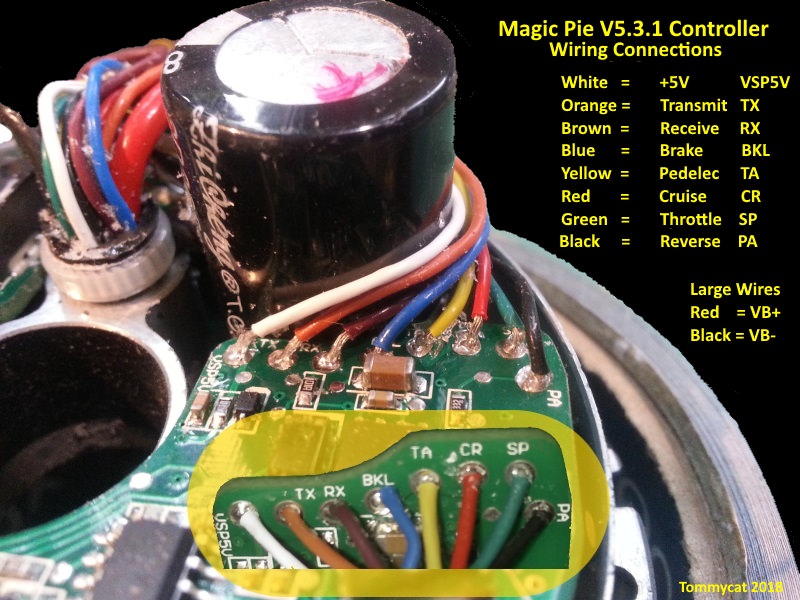
I was unable to find a matching 8pin connector available so I got a universal throttle (male juliet) from ebay and a (female juliet) to bare 3 wire (black, white, red). I tested the continuity between the 3 pins and wires and compared it to the diagram presented on ebay for the +, -, and 5V pins.
I cut the 8pin off the controller end and tested DC voltage on the controller wires with a multimeter and found 2 combos gave ~50V, one gave ~55V, and the others gave very small amounts. I assumed the combination that gave me 55V was the +/- in correct order that the multimeter was reading positive voltage and not negative.
I then tied the +'s together, -'s together and tried the white 5V throttle wire against each controller wire. None of these allowed the throttle to work. I then tried it with the + wire going to each of the 50V wires instead of the 55V. Still the throttle did not do anything. Then I accidently jumped what I thought were the positive and negative (read 55V) and the motor spun. I was hopeful at this point but got a little jump happy and decided to just try some combinations. I found that one of the 50V wires jumped to the "negative" also made the wheel spin, but then the motor made a whistling/whine sound. And now jumping does not spin the motor. Now when I turn the battery on, the controller whines/whistles.
What have I damaged? What will fix it? A new controller? Replace a piece on the current controller? I am also contemplating a new cheap rear motor that is ready to accept a standard 3 pin throttle if the fix seems too time consuming or expensive as a front hub motor doesn't seem ideal for my uses, but will try fixing it if its cheap!
Also, what did I miss as the proper way to use a multimeter to test which wire goes where from the throttle without getting jump happy and breaking things? I feel like I was close to being able to tell which wire went where but am lacking some information.
Thank you for any and all advice fellow tinkerers!
link to Short video of whine/whistle soundIt's possibly a Gen 2 or up to a Gen 4. It's been hard to find enough info to determine and the company has been unresponsive. It has an internal controller.
I was unable to find a matching 8pin connector available so I got a universal throttle (male juliet) from ebay and a (female juliet) to bare 3 wire (black, white, red). I tested the continuity between the 3 pins and wires and compared it to the diagram presented on ebay for the +, -, and 5V pins.
I cut the 8pin off the controller end and tested DC voltage on the controller wires with a multimeter and found 2 combos gave ~50V, one gave ~55V, and the others gave very small amounts. I assumed the combination that gave me 55V was the +/- in correct order that the multimeter was reading positive voltage and not negative.
I then tied the +'s together, -'s together and tried the white 5V throttle wire against each controller wire. None of these allowed the throttle to work. I then tried it with the + wire going to each of the 50V wires instead of the 55V. Still the throttle did not do anything. Then I accidently jumped what I thought were the positive and negative (read 55V) and the motor spun. I was hopeful at this point but got a little jump happy and decided to just try some combinations. I found that one of the 50V wires jumped to the "negative" also made the wheel spin, but then the motor made a whistling/whine sound. And now jumping does not spin the motor. Now when I turn the battery on, the controller whines/whistles.
What have I damaged? What will fix it? A new controller? Replace a piece on the current controller? I am also contemplating a new cheap rear motor that is ready to accept a standard 3 pin throttle if the fix seems too time consuming or expensive as a front hub motor doesn't seem ideal for my uses, but will try fixing it if its cheap!
Also, what did I miss as the proper way to use a multimeter to test which wire goes where from the throttle without getting jump happy and breaking things? I feel like I was close to being able to tell which wire went where but am lacking some information.
Thank you for any and all advice fellow tinkerers!