Golden Motor External controller

Jhurt500

1 µW
Joined
May 26, 2022
Messages
3
This may be a dumb question but I am trying to install the universal external controller from Golden Motor on my magic pie 3 and several of the connections call for red wires coming from the harness into the controller connections. I only have one red wire. How do I make this work?
 
We'll need to know exactly what you have and where the wires go / what voltages they have before we can tell you. Red wires could be for literally anything, so we need to know what red wire you have, what it is for, and what red wire(s) are called for by the specific connections you need to connect to.

If you don't know any of those things yet, then links to the specific parts you've bought may help, along with pictures of the wires you have there, labelled for where they come from on the bike or motor. We might have to have you make measurements with a multimeter once we see what you have.
 
This is the diagram I am following
Although any color wire can be used for almost anything when it comes to Chinese components, there are generally two voltage levels used for red wires that provide power. For the existing wires going to your Magic Pie, the fat red wire is the battery source B+ wire, powering the internal controller. This is the wire that would go to the battery input of your new controller. B+ is also used for the "key switch" on controllers, used to turn the controller on and off.

The rest of the red wires used for power are usually 5VDC used to support various control inputs, like the throttle, PAS sensor, three speed switch, brake cutoff, if your controller has those inputs. Your input devices may or may not use red as the color convention for the 5VDC source, so may take some trouble shooting before connecting them up to the new controller.

Things like lights or alarms are a mixed bag between battery level voltage or 5V, or something else (12VDV), if they use red wires.
 
I ride a Magic Pie V5 and can totally understand your desire to keep this fine motor going.

Overview: As your changing the location of the internal controller to outside the motor housing. The motor's wiring which includes the 3 larger phase wires, as well as the 5 smaller hall sensors wires. Must be extended to where the new controller will reside.
The existing 8 pin wiring harness with the wiring to the peripherals will then go directly to the new controller location, as well as the battery wiring.

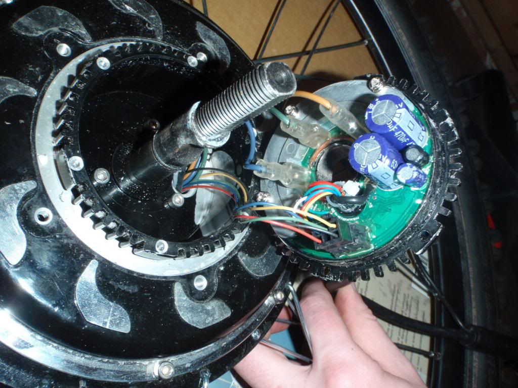
Internal Magic Pie 3 controller...

Phases: Large YELLOW, GREEN, and BLUE single connections. Halls wires go to BLACK 6-pin connector.


4_zps406bca35.JPG


At the controller to phase connections, I would recommend bullet connectors to aid in changing the phase to hall configuration if needed. Or at least be prepared to swap leads before final connections made.

May be a great time to add a temperature sensor to the motor. Especially if you plan on pushing it harder than normal.

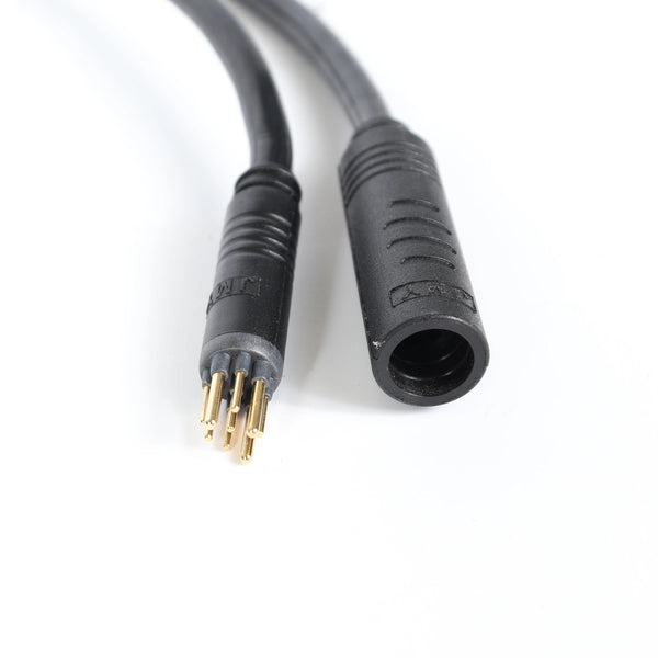
If I were to do it, I would procure a 9-pin motor connector and harness length that would reach my new controller.
This would have the extra-large needed phase wire in it. And allow easy removal of the motor and wheel with a HIGO connection.
Considerations would be that the phase wires be of sufficient size to carry your maximum current. And that the cable outside diameter would fit thru the axle opening.
An example...

IMG_3931.jpg

As seen here...
Just an example.

See this link for example pictures of the motor's wiring connections and information. (Other links are in this thread...)
Magic Pie 3 controller - end of the game? How to salvage great MP3?


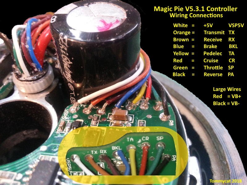
As far as the upper harness connections to the controller go, I do not know of any verified wiring color aids such as the one below for the M.P. V5... although the second MP3 harness picture shown below has some.

xgCBFbd.jpg


In your case you will have to carefully identify or verify what color of wire goes to each pin at the 8-pin motor harness connection.
And label them accordingly to which pin they go to at the top pin connectors. I.G. Throttle, Brake, Grounds ECT.

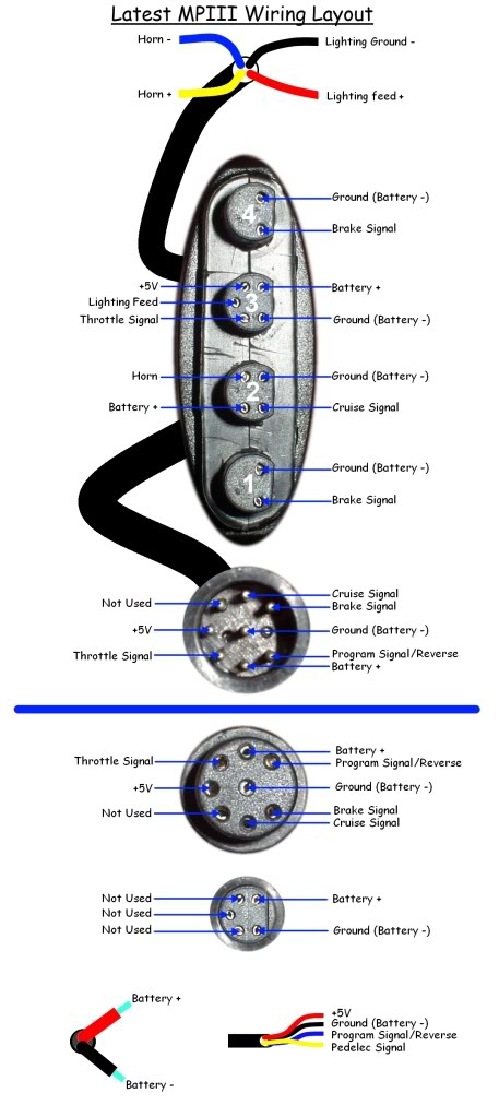
Now there seems to be 2 types of MP3 harnesses that I've seen... hopefully one matches yours.


LatestMP3wiring.JPG

And this one...
fetch


This careful identification and verification of wiring colors may be helpful to others in the future... (hint, hint)

Then just match up your controller's wiring to what to hook up too.

Please note that your controller requires a "key lock" connection to power it up.
Something extra not found on the original Pie.


Regards,
T.C.
 
Last edited:
This may be a dumb question but I am trying to install the universal external controller from Golden Motor on my magic pie 3 and several of the connections call for red wires coming from the harness into the controller connections. I only have one red wire. How do I make this work?

I didn't even know they still make Golden Motor stuff, is Luna still supporting that?
 
Yeah the colors wont match up, means you have to decode from wires of known and unknown and look back to see what the markings on the pcb board say and go from there. Maybe take some pictures, maybe someone will know the circruitry of what is what by the chips but good luck on that.
 
I didn't even know they still make Golden Motor stuff, is Luna still supporting that?
I believe that Luna stopped stocking the Pie around 2019, and have sold out most of, if not all their replacement parts…
But the Pies are still alive and well being sold by Golden Motors Canada.

E-Bike Hub Conversion kits


But the best for technical support would be the Golden Motor forum. Where Bikemad is the ultimate source of knowledge of all things Pie.

Golden Motor Forum
 
Back
Top