Bluetooth DC energy monitor

Great to see some recent posts this year, I hope you get time to work on this soon.

I'd be interested in a few of these if/when you get to that point. For my personal application, waterproofing isn't a big deal - a lot of other power meters I see aren't waterproof, nor are some of the other electronics I'm using. "Splash-resistant" is probably enough, with the idea that it would be protected in a bag/case (or not used in heavy rain).

Regarding your display (power) issue, while the LCD looks awesome, could you use something smaller and only show one stat at a time (with a button to cycle through - possibly also have it 'sleep' and only go on when the button is pressed). Maybe even just use a 4 digit 7-segment display?


I came across this thread while looking for a simple/cheap power meter, mainly for stationary application (but also for my ebike if it's good enough). I don't suppose you have any old prototypes you'd be willing to part with, or if you'd be willing to post details of the design (even just partial, or old versions)?

I'm wanting to monitor bidirectional current to about a dozen 48v battery packs simultaneously, and don't need many of the features, just some way to log the current every few seconds. I've been trying to make something myself (shunt + INA226 + arduino or ESP8266) but my prototypes keep failing. I think noise filtering is my issue, I just don't know much about it. So even just your circuit for the INA226 would be of great help to me!
 
houncir said:
Great to see some recent posts this year, I hope you get time to work on this soon.

I'd be interested in a few of these if/when you get to that point. For my personal application, waterproofing isn't a big deal - a lot of other power meters I see aren't waterproof, nor are some of the other electronics I'm using. "Splash-resistant" is probably enough, with the idea that it would be protected in a bag/case (or not used in heavy rain).

Regarding your display (power) issue, while the LCD looks awesome, could you use something smaller and only show one stat at a time (with a button to cycle through - possibly also have it 'sleep' and only go on when the button is pressed). Maybe even just use a 4 digit 7-segment display?

I came across this thread while looking for a simple/cheap power meter, mainly for stationary application (but also for my ebike if it's good enough). I don't suppose you have any old prototypes you'd be willing to part with, or if you'd be willing to post details of the design (even just partial, or old versions)?

I'm wanting to monitor bidirectional current to about a dozen 48v battery packs simultaneously, and don't need many of the features, just some way to log the current every few seconds. I've been trying to make something myself (shunt + INA226 + arduino or ESP8266) but my prototypes keep failing. I think noise filtering is my issue, I just don't know much about it. So even just your circuit for the INA226 would be of great help to me!

Sorry I never replied to this. I've had some time recently to work on this project again. I have started redesigning the hardware from scratch. The new version is not designed to be waterproof, however it should be somewhat resistant to dust and small splashes from most angles.

Even a smaller or 7-segment display still uses too much current. Just a few milliamps is enough to start heating the board at 60V. I have now switched to using a micro synchronous buck converter IC with integrated switches (LMR36503). This is capable of 65V or 70V absolute max.

I still only have the two prototypes so I'm not willing to part with them. I did attach a schematic earlier in the thread. My implementation just used an RC filter on the inputs as per the datasheet. I didn't have any problems with transients in my limited testing but may look into further protection as per this app note: https://www.ti.com/lit/ug/tidu473/tidu473.pdf
 
lower the brightness. especially with green leds you need very little current to get usable visiblity from it.
 
More info on this next hardware revision.

I switched to the INA228/229 current shunt/voltage monitor. This has a built in temperature sensor for the current shunt. Along with this change, I removed the reverse voltage protection and voltage divider and changed to high side current sensing.

I decided to go with the newly available Fanstel BC833M Bluetooth module. This is based on the nRF52833 which comes with some nice features like double the RAM, faster SPI, higher transmit power, long range BLE PHY, and even BLE direction finding. The module has a better antenna than the previous one I used. While the metal connectors under the antenna aren't ideal I've made several changes to the layout which should improve the range.

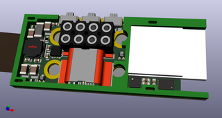
I flipped the main PCB over so now the components are sandwiched between the PCB and the XT60 connectors. The display is attached to the reverse side of the main PCB. This has the advantage of protecting the components, making the device much smaller, requires only one single sided PCB for automated assembly (solder the LCD is a simple manual or semi-automatic operation) and prevents the LCD shielding from interfering with the RF signals so much. I think the XT60 connectors can now be soldered with a selective soldering machine. I have a mostly milled out 1.6mm PCB that sits between the main PCB and the connector to provide additional support and protection. I'm not sure if milling will work for such thin edges though, I might need to look into laser cutting.

I'm trying to add a piezo sounder, but I'm still looking at ways to add it without any manual soldering involved. One method could be to use vertical pogo pins in place of two header pins.

There is a small plastic cover that sits between the XT60 connectors. This will hopefully also have covers for the three buttons which space them out more, or I might have to move to just two buttons. I think the cover should be able to be 3d printed in lower quantities.

The LCD has another milled out PCB or panel surrounding it and a polycarbonate label with a transparent viewing area is applied on top.

The BOM cost has gone back up (partly due to increasing costs of the parts themselves) but I think the device is now more manufacturable. The INA228/229 adds a bit of cost which could admittedly be lowered by using one of the other pin compatible 85V current shunt monitors. Still, to manufacture in NZ I would need to do a run of 1000 units to reach $100 NZD ($73 USD) sales price. If I had that price for a run of 100 units it wouldn't' be too bad. I'll shop around a bit more and maybe look at using Chinese PCBA services.

I've mostly finished with the high level hardware design. Next I'll create a new schematic and then do the layout for real. At the moment the components are just placed somewhat randomly to ensure they'll fit.

Also, Runtime.io, the company behind development of Apache MyNewt was bought out by JUUL Labs some time ago and is not contributing any more. It seems like development on MyNewt has slowed down a lot. It's a bit hard to get answers to all my questions as there isn't a really big community and last time I looked much of the documentation was out of date. That said, it is not that complex and given enough time I can find most the answers myself. I really do like MyNewt but I will look at whether switching to Zephyr or RIOT would be better.


flippy said:
lower the brightness. especially with green leds you need very little current to get usable visiblity from it.

If the device is to work above 60V, e.g. up to 120V, my budget is only 3mA or so if using a linear regulator. More than that is possible but while it wouldn't stop the device from operating, it would cause a lot of heat. And most of that is already used by the nRF if transmitting continuously. The LCD I'm using draws 15mA for reference. There are lots of cool things I can do with the LCD as well. Maybe I could look at making a 120V version if this one is successful.
 
try one of those green 7 segments, you can run those in the microamp range and still be visible in a room.
and 120V would be extremely useful. that would cover 20S batteries wich is the most common.
 
flippy said:
try one of those green 7 segments, you can run those in the microamp range and still be visible in a room.
and 120V would be extremely useful. that would cover 20S batteries wich is the most common.

I'll have a play with those sometime. For now though I've settled on the DC-DC converter for this model as the increased efficiency (even with display off) and the LCD are most useful for me and my intended use cases. If I made a 120V model I'm not sure if it would need an onboard display though. It would probably be mostly used on ebikes where a bluetooth connection or external display might make more sense. Although it could be useful for off bike charging. The first hardware revision should already work on 120V if the display is not plugged in (I've only tested to 60V).

Another option to retain the LCD for a higher voltage model if only 95-100V is needed would be to use a LM5009A or LM5019 buck converter. They're a bit difficult to fit on this board design however. And I would need to go back to low side current sensing as 85V is not really enough margin for 20S.
 
Back
Top