BMS design help needed

Skippic

100 W
Joined
Jun 22, 2010
Messages
224
Location
Bratislava, Slovakia
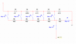
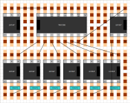
My intention is to make an Arduino driven BMS. This is for a 24s LiPo pack. The idea is to use a multiplexer to turn on a solid state relay at each cell connected in series with a resistor and an analog optocoupler (in parallel).

file.php


It should work by checking the voltages once every minute (while charging or in use), if it detects a cell below 3.6V it sends LVC signal.
If the pack is charging and the max voltage is more then 4V and a cell is 0.1V above the lowest cell it discharges the highest cell for one minute.

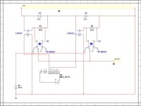
I need help selecting the most suitable components. At the moment the best solid state relay I found is the LH1547 at about $0.90 a piece shipping included. It's max current rating is 120mA (a little low). But since it will be balancing every charge and I will use a charger of my own making, so the BMS can turn it on and off as many times as I like to get the pack balanced and fully charged it should be OK.

My biggest problem is searching for analog optocouplers. I've been able to find the HCNR201 at $3.10 each. That's $74.40 for optocouplers! Is there a cheaper analog optocoupler? It doesn't need to be perfectly linear, just give consistent output values at the same input for all the cells.

Just to avoid multiple posts: yes I'm using the same circuit for measuring and discharging the cells. The difference is, that for measuring all that is needed is a few ms, while for discharging it's in order of minutes or hours.

I'm also thinking of placing a small capacitor in series with the optocoupler, so it doesn't burn the LED when discharging.

Originally the idea was to use a separate MUX for reading the opto values, but maybe I can use them connected with common output or at least through resistors with reduced sensitivity. Can someone tell me what is the best solution here?
 

Attachments

  • BMS.JPG
    BMS.JPG
    51 KB · Views: 740
I skimmed it.... (as requested via PM)

Where/how are you measuring the voltage on the cells?
That is the whole crux of the problem... obviously you cant use the 10bit A/D on the Arduino to measure them directly.
Flush out that schematic to show how you are measuring the cells

There is a reason why folks do it one of two ways: Either they top balance (Gary Fechter) or they use a COTS part (methods w/LTC).

Dont worry about component prices now - just set aside $1k to get a prototype working and reassess at that point.
Assembly will probably cost you much more than components if you cant do large volume.

Might I suggest you use the parts I am using on my HVC LVC boards... they could definitely trigger your HVC LVC opto's (like a Switching regulator)
All I see now is that you have feedback that tells you when your shunts are active. I would eliminate that as it is redundant. You either trust your SSR or you dont. Monitoring the cell voltage will tell you if your shunts are active. Temperature can tell you that too.

-methods
 
Thanks for your input.

methods said:
Dont worry about component prices now - just set aside $1k to get a prototype working and reassess at that point.

This project is not meant for mass production, it's basically just for me and anyone, who would like to learn from my mistakes ;)

As always I manage to confuse everybody by going too specific and not explaining the basic principle of what I'm trying to do.

So let me correct that mistake:
I would like to measure cell voltages with an Arduino Nano. There are of-course two problems with that.
1. since the cells are connected in series the voltage is far too great to monitor directly
2. the Arduino has only 8 analog inputs, not sufficient for 24s cells

My first idea was to use a resistor voltage divider to bring the voltages to the range of the Arduino, but apart from the loss of precision it would drain the battery all the time.
So I thought of using analog optocouplers. The thing is, that I have no real idea how they work. I think I'll just order a few, so I can test them.

The second problem with only having 8 analog inputs should be solved by using multiplexers.

Since I also want to have the possibility to balance the cells the idea is to discharge them through the SSR and a resistor.

So here is how it should work:
- the Arduino selects the first port on the MUX
- that sends a high signal to the SSR connected to cell No.1
- the SSR goes ON and lets full voltage from cell No.1 to both the discharging resistor and the optocoupler (which might need a resistor itself, to limit the input current)
- the signal from the output of the optocoupler can be read by the Arduino (At this point I'm not sure, if I will need another multiplexer, or if it can be solved in another way. In the schematic all the outputs are connected together, hoping the highest voltage would prevail. If they work as transistors that should be the case. Only one opto would be running at a time.)
- the 43ohm resistors are used purely for discharging and should limit the relay current to 120mA (max current)

After that:
- the Arduino selects the second port on the MUX
- it can now read and discharge cell No.2

And so on...

The LVC and HVC are set in software. The only signal the Arduino gets, is the voltage of each cell.
 
OK, so I had a closer look at the working of the HCNR201 and it requires op amps to make it work. It wouldn't be a problem if all parts needed wouldn't have to be multiplied by 24...

Therefore I'm left looking for a part that does the following:

Unknown part.jpg
- input voltage 0-5V
- Vcc can be anywhere from 5-100V
- output voltage should be equal to input voltage and more or less linear
- price-wise up to $5/each
- and obviously isolation between the cell side and the measuring side

I think if I find this part, the rest should be easy :D
 
Contact Mouser and ask if they carry or can get anything like that. They tend to have pretty good help with that sort of thing.
 
PROGRESS!!!

I spent the whole night thinking and came up with a workaround.

Well, it's a worse solution, but simpler and therefore cheaper. My only fear is the precision of the measurements.

It uses a resistor voltage divider as was my first idea, but it's controlled by relays (SSR), so there is no unwanted discharging. Plus this way only one resistor/cell is needed.

Since more relays need to be operated at the same time, the MUX will be replaced by a shift register. One thing I kind of copied off methods, is doing separate boards for each 6s pack. It's more modular and simpler to make.

Here is a basic scheme (the switches are SSRs):
file.php


J6 and J7 + one of J1 - J5 are used to measure voltage on cell 1- 5
J1 gives voltage GND - cell 1
J4 gives voltage GND - cell 1 + 2 + 3+ 4


To discharge cells 2 and 3, J3 and J5 need to be connected.

I also considered placing SSRs between resistors for absolute freedom of discharging combinations e.g. cells 5, 3 and 1 (disconnecting R4 and R2 and connecting all but J7), but I believe balancing is not a great deal if it's done with every charge, therefore even the dumbest discharging system should be good enough. At present any string of consecutive cells can be discharged at the same time. If needed, in the future additional SSRs could be placed between resistors (maybe one for each 6s board).

As for the measurement precision, there is one trick I have up my sleeve ;)
The Arduino analog input has a precision of 10bits (1024 values). That would leave a precision of 100V / 1024steps = 0.098V/step. That's pretty bad. Here is my solution:
Precision booster.png

Consider the precision is 0.1V/step. The output from the circuit is 4.01. The Arduino would measure 4.0V.

Now by moving the analog from 4.0V down until the result is 3.9V you arrive at lets say 2.91V. Then the same process is repeated going up from 4.0V until the result is 4.1V and the analog is at 4.91V.
Now if I'm not mistaken calculating:
4.91V - 4V = 0.91V to get to 4.1V
4V - 2.91V = 1.09V to get to 3.9V

(0.91V + 1.09V) / 0.2V (error) = 10 (coefficient of precision)

4V + (1.09V /10) - 0.1V = 4.009V (much closer to the real value of 4.01V)

The R7 should in this case be 10x bigger than R6 if I'm not mistaken.
 

Attachments

  • Resistor divider.png
    Resistor divider.png
    6.9 KB · Views: 632
amberwolf said:
Contact Mouser and ask if they carry or can get anything like that. They tend to have pretty good help with that sort of thing.

Thanks for the idea. Where I come from, clerks at stores with electronic components look bad at you if you don't know what you want ;)

I got a reply:
OPIA4010DTU - 4 pins 2 IN, 2 OUT analog signal.

If I can do it with just SSRs and a resistor divider as stated above, I'll go that way. I understand the precision may suffer a little, but if it's within 0.02V it should be usable. Using th optos could introduce other complications apart from more parts.

Here is a sketch with the component placement:
file.php


Replacing the LH1547 by an IC, that contains more SSRs would help a lot! Any ideas?

Emil
 

Attachments

  • Component placement.png
    Component placement.png
    16.6 KB · Views: 632
I've made some progress. It looks like the SSRs have a pretty big resistance in their on state the LH1547 specifically 12-34ohms. If that was constant, it would be no problem, but it also varies with temperature. Therefore if say cell 3 was above the desired value, it would get discharged and while doing so, heat up the SSR giving it a higher resistance for the measuring phase. The best I've been able to think off is measuring while at room temperature and then discharging by calculation. Say we need to discharge 0.1V with 10Ah pack, we can calculate the exact charge that needs to pass through the SSR. However depending on the battery chemistry and the current cell voltage the capacity varies. Could someone point me towards where I could find these values? I mean like LiPo between 4V and 3.6V has a linear capacity/voltage characteristic and it is 80% of the battery capacity. Especially for values between 4 - 4.3V.

Another solution is getting a temperature sensor (I just got 4 x LM35DZ), covering all the SSRs with a plate of aluminum acting as a heatsink. By measuring the temperature of the SSRs one can easily calculate their resistances.

One more option is getting SSRs with low resistance (I've seen some with 0.1ohm), but they are usually limited to 60V.

A combination of the above would no doubt be sufficient.

Finally some good news:
The values of the resistors and of the SSRs will never be all exactly the same. So instead of getting precise components I've decided to do a little one time calibration procedure for each board. It consists of applying the same voltage to all the inputs (like if just one cell was connected to all the SSRs). By that, one instantly has the exact resistances for all the paths. All that is needed is a plug with all the balancing wires joined and plugged into a 5V reference.
 
There are small MOSFETs with 1 Ohm and less ON resistance, I guess that could replace your SSRs.
 
Njay said:
There are small MOSFETs with 1 Ohm and less ON resistance, I guess that could replace your SSRs.

But would they isolate the Arduino? I tried using SSRs to get optical isolation. Can you suggest a specific part, so I can learn more? ( I'm a complete noob at this ;) )
 
You can (will have to) use optical couplers between arduino and the MOSFETs. BS170 is a typical part, but with around 1.2 Ohm ON resistance. Go for example to on-semi site and do a parametric search on MOSFETs in TO-92 (through hole) or SOT23 (SMD) package devices with low RDS(ON). I never designed with these, but that's a possibility I would explore.
 
Back
Top