BMS replacement questions

rick_p

100 W
Joined
Feb 16, 2021
Messages
260
Location
Los Angeles
A friend gave me a 36 volt battery he was no longer using and thought was in working condition, which is understandable because he was good about topping off the charge every few months and the charge indicator LEDs show a full charge. However, when I tested it at home there was no voltage at the discharge port. The fuse is not accessible from the outside of the battery so I had to open it up and look for the fuse inside. Once inside I found the fuse and it was fine, no signs of overheating at the terminals of the fuse holder, but then I saw this and figured this can't be good.

bms-pos-wire.jpg

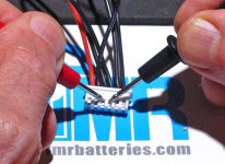
I cut away the shrink wrap to get a better look because clearly that solder connection got very hot at some point. I'm only a novice at best when it comes to battery internals but I know enough to check the basics, most of what I learned I did so on this site, or from watching videos. As you can see in the picture below, the terminal that got hot was the positive supply from the cells (P+) to the BMS. I tested the voltage at P+ and P- and got zero voltage, I got 40 volts at P+ and B- which I believe tells me the cells are fully charged but the BMS has shut down and not allowing the voltage to pass through to the discharge port.

bms-voltage.jpg

The question I have is, is it safe to assume that the problem is the BMS itself went bad or is it more likely that something else went wrong which caused the heat at the P+ solder connection, and then the BMS just shut down to prevent fireworks, and the BMS is working and just doing what it's supposed to do?

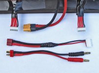
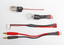
If the BMS went bad, and the battery can be fixed by replacing it, I'm comfortable doing the work, there are videos that show how to do it safely and I have the soldering skills, but I did some shopping for the 10s 36v BMS and I didn't find any with the same wiring configuration. This is where my lack of experience might be an issue. In the photo below you can see that the main harness doesn't have balance wires in every port, is that typical of a 10s 36v battery? Also, none if the BMSs I saw showed terminals to solder the wires to that go to the charge indicator LED circuit board, which is just to the right of the main harness in the picture below. Lastly, there are two white wires soldered to the BMS just to the right of charge indicator wires, which I figured are for a thermal sensor, but if they are, I will need to remove a lot more shrink wrap to trace where they go.

harness-wires.jpg

I would love to use this battery, and it seems fixable, but I could use a little guidance here. Thank you
 
The battery is certainly salvageable if the cells are good. Replacing the BMS isn’t a huge deal if you are willing to stop looking for a plug-and-play replacement for the BMS balance wires and are willing to solder new balance leads to the parallel cell groups.

Before you do all that, though, try charging the battery. Sometimes BMS’s go to sleep after long periods of inactivity and just need “woken up” by 3 seconds on the charger.
 
The battery is certainly salvageable if the cells are good. Replacing the BMS isn’t a huge deal if you are willing to stop looking for a plug-and-play replacement for the BMS balance wires and are willing to solder new balance leads to the parallel cell groups.
I didn’t check the balance on the cells to see if maybe one was bad, but the fact that it takes a charge and is showing 40 volts when you bypass the BMS are both very good signs. I’m not opposed to soldering on new balance wires, I just hope I can find a BMS that supports the charge indicator LED circuit board, I hate to loose that functionality on the battery.
Before you do all that, though, try charging the battery. Sometimes BMS’s go to sleep after long periods of inactivity and just need “woken up” by 3 seconds on the charger.
Thank you for the suggestion. I had tried that already but I tried it again after disconnecting the BMS because I read somewhere that disconnecting it is another way reset them, but no luck.
 
You do have to check all 10 group voltages to see what they are. At 40V, it's likely all ten are at 4.0 volts each, but as part of the error check, it's something that should be done to verify that the BMS is bad. To cherry pick a situation, you could have 40V with 9 groups at 4.1 charge which gives you almost 37V, and if the tenth one is at 3V, the BMS is on the verge of shutoff for discharge,

Plugging in the charger should have reset the BMS, but try to reset the BMS by unplugging the harness and plug it back in. Usually they will shut off if that exposed lead short circuited and given a few minutes, will turn back on.
 
Last edited:
You do have to check all 10 group voltages to see what they are. At 40V, it's likely all ten are at 4.0 volts each, but as part of the error check, it's something that should be done to verify that the BMS is bad. To cherry pick a situation, you could have 40V with 9 groups at 4.1 charge which gives you almost 37V, and if the tenth one is at 3V, the BMS is on the verge of shutoff for discharge,
Well, I guess my next step is to remove all the shrink wrap and related protective coverings so I can access the groups for testing, I don’t want to attempt testing at the tiny harness, it’s too easy to short circuit that way. Besides, I’ll need all of that out of the way to solder the new balance wires.
Plugging in the charger should have reset the BMS, but try to reset the BMS by unplugging the harness and plug it back in. Usually they will shut off if that exposed lead short circuited and given a few minutes, will turn back on.
I did that already, it was disconnected for several minutes, no luck there.
Years ago, I also put in a plaintive cry to find the exact BMS for a replacement.Yes, you have to use a generic BMS. They all use the same connections to P-, C_, and B-. Sometimes they even use the same balance harness, but you cannot always tell from the picture. The first BMS I bought, I thought it used the same balance connector, but it was a different size.
Like I was saying, I don’t mind soldering on new balance wires, but so far I haven’t found a BMS that has the connection for the charge indicator. If I loose that function, so be it, but I’ll keep looking.
 
Like I was saying, I don’t mind soldering on new balance wires, but so far I haven’t found a BMS that has the connection for the charge indicator. If I loose that function, so be it, but I’ll keep looking.

Charge indicator being the little push-button on the side of the battery that, then pressed, lights up a series of LEDs to indicate a very rough state of charge? In all my experience, those are wired directly to the battery, not the BMS. Take another look and see if that isn’t the case for yours, too.

If / when ordering a new BMS, be sure to take into account physical size. It can sometimes be the hardest attribute to match or get close to, but is very important if the battery needs to go back into a case.

ES member Methods did some very good work recently, on his own dime, to reveal that DALY brand BMSs may not be super reliable. I was bummed at this news, having chosen those units for some of my own projects — but may be best to consider a different brand. As with many electronics, you get what you pay for.
 
Another complication is whether the battery has an ON/OFF switch. If it does, almost always a low current switch that switches the BMS. so you need a BMS to support the switch,

In my experience, inexpensive batteries do not use balance BMS. Not on mine, anyway. I have bought BMS that balance to upgrade existing batteries. Make sure the BMS spec lists a balance current if it advertises "balance". Sometimes they just mean you get the balance harness.
 
I just hope I can find a BMS that supports the charge indicator LED circuit board, I hate to loose that functionality on the battery.
You'd have to show a picture of that part to better guess, but the typical such board (with a little button to check the charge so it's not on all the time draining the battery) just has a plus and minus wire that connects to either the main cell block plus and minus, or the main cell block plus and the BMS minus either C- or P-. The BMS doesn't really have anything to do with such boards; they're independent in all the cases I've opened up to work on a battery that had one.
 
Charge indicator being the little push-button on the side of the battery that, then pressed, lights up a series of LEDs to indicate a very rough state of charge? In all my experience, those are wired directly to the battery, not the BMS. Take another look and see if that isn’t the case for yours, too.
If you look at the image with the name wiring-harness.jpg full size you can see the red and black wires connected to the BMS, but I’ll look carefully to see if it’s possible to determine if it’s the same as connecting directly to the battery wires.
If / when ordering a new BMS, be sure to take into account physical size. It can sometimes be the hardest attribute to match or get close to, but is very important if the battery needs to go back into a case.
Good point, will do.
ES member Methods did some very good work recently, on his own dime, to reveal that DALY brand BMSs may not be super reliable. I was bummed at this news, having chosen those units for some of my own projects — but may be best to consider a different brand. As with many electronics, you get what you pay for.
Great tip, thanks!
 
Another complication is whether the battery has an ON/OFF switch. If it does, almost always a low current switch that switches the BMS. so you need a BMS to support the switch,

In my experience, inexpensive batteries do not use balance BMS. Not on mine, anyway. I have bought BMS that balance to upgrade existing batteries. Make sure the BMS spec lists a balance current if it advertises "balance". Sometimes they just mean you get the balance harness.
No on/off switch, the button only shows state of charge, the lights go out when you let go of the button. Thanks for the tips, I’ll be careful with the purchase.
 
What happens if you remove or disconnect BMS and just run it? Will it charge up almost balanced then? I say that because a bms may cost more than older pack is worth. And bms swap may fail.
 
What happens if you remove or disconnect BMS and just run it? Will it charge up almost balanced then? I say that because a bms may cost more than older pack is worth. And bms swap may fail.
I haven't gotten that far yet, I still need to check the current balance to look for any telltale signs of a bad cell. If the current balance is good (all the cells are properly balanced) it will be worth the cost of a BMS and the time to install it.
 
You'd have to show a picture of that part to better guess, but the typical such board (with a little button to check the charge so it's not on all the time draining the battery) just has a plus and minus wire that connects to either the main cell block plus and minus, or the main cell block plus and the BMS minus either C- or P-. The BMS doesn't really have anything to do with such boards; they're independent in all the cases I've opened up to work on a battery that had one.
bms-led.jpg
I'm certain the first image is the source of the BMS failure, I knew there was an instance of heat buildup but it wasn't until I flipped it over that I knew there was damage for sure. Now I just need to test all the cells to make sure none of those were damaged in the process. The middle image is the LED circuit board with button, and the image on the right is where the wires from it connect to the BMS. I understand this is not typical, but since that did it that way I'm still not sure if it would be safe to connect it directly to the main battery lines as you and others have suggested, so if I end up with a BMS that doesn't support it, it's not big deal, I can live without it. The maker and model of the BMS is stamped on the back but the maker doesn't sell to the public and I'm not finding one available anywhere else.
 
I'm certain the first image is the source of the BMS failure, I knew there was an instance of heat buildup but it wasn't until I flipped it over that I knew there was damage for sure. Now I just need to test all the cells to make sure none of those were damaged in the process.
The part is marked D3, and it's probably a power diode. I can't tell what it's connecting across, but if it is in series with the negative current path for discharge (between BMS FETs and the P- pad) then it would have to take the entire current of the whole system, and could overheat if the system is used at a higher current than designed for, or if the diode/BMS is enclosed where there is no airflow or any way to shed the heat generated.

A diode in the above position, wired in that way, is not actually necessary for the BMS to function and may have been used as a "fuse" to prevent overcurrent usage of the BMS/battery, instead of an actual fuse, for whatever reason.

It would also prevent regen braking from working normally (or at all) as current couldn't feed back thru the diode into the battery (and another way it could fail is if regen braking was used and the generated voltage rose so high it exceeded the diode's breakdown voltage...but that would probably have also damaged the controller's FETs).

If it's on the charging circuilt (C-) then it wouldn't affect output (discharge) only charging (input).

If it's on the B- or B+ instead, then the BMS would be completely disconnected from the cell block and there will be no power anywhere on the BMS to operate it or pass thru to the controller/etc. (it also won't charge).

It's unlikely the cells have any problems from the diode failure (but testing them doesn't hurt and will tell you something about the state of the battery as a whole).


The middle image is the LED circuit board with button, and the image on the right is where the wires from it connect to the BMS. I understand this is not typical, but since that did it that way I'm still not sure if it would be safe to connect it directly to the main battery lines as you and others have suggested, so if I end up with a BMS that doesn't support it, it's not big deal, I can live without it.
The LED meter board looks just like others Iv'e seen that just directly connect to the battery. If it's still working, then if you measure battery voltage at the red/black wire pair, then any points within the battery that give you battery voltage will work with the board.

The only caveats are:

--if you connect the meter board directly to the cell block, then the BMS (whichever one you use) can't protect the cell block from being drained by the meter board under any circumstances that might happen.

--If you connect the meter board positive to the cell block (or BMS positive, they are the same point electrically), and the meter board negative to the BMS P-, then if the BMS shuts off output for any reason, the meter board can't read the battery voltage correctly (or at all). But this is where I would recommend connecting it, since that itself will tell you something if your bike powers off while riding.

--If you connect the meter board positive to the cell block (or BMS positive, they are the same point electrically), and the meter board negative to the BMS C-, then if the BMS shuts off input for any reason, the meter board can't read the battery voltage correctly (or at all) (it would still read the charger itself though, if connected).


In the unlikely event that the red/black wires to the board don't have battery voltage on them when the LED board is operating normally, then I'd expect at least three wires from the BMS to the LED board, so that it would have power, ground, and a serial data line...but I doubt it is anything that complicated.
 
It's unlikely the cells have any problems from the diode failure (but testing them doesn't hurt and will tell you something about the state of the battery as a whole).
Thank you for all the great info on the BMS and LED board, I will absolutely keep all that in mind when I get there. I quoted your comment about testing the cells because that is where I’m at with this repair, and I agree that it’s a good test for the general state of the battery, but I had to put this on pause for a moment because my daily commuter broke on my way home from work the other day, and I had to focus on that so that I have transportation, this battery is just a side project.

Thankfully, the part that broke on my bike isn’t part of the ebike system, it’s just a regular bike part, the freehub on the rear wheel started spinning freely in both directions, and since this is a mid-drive bike it meant no drive from the peddles or the motor. I just finished that repair last night, so my commuter is back on the road. I plan to test the cells this evening.
 
Side note to this conversation, after searching for a replacement BMS and finding it a challenge to find one that will fit in the space where this one was, either because the generic ones are too big or they don’t provide the measurements at all, I have come to realize I may either have to get creative and have the BMS on the outside of the case, or maybe not use a BMS at all. I watched a good video on using a balanced charger instead of a built in BMS on the battery, and I have to say, it’s very tempting. In either case I’m going to be drilling holes in the case, and an external BMS will be more challenging to mount and protect than balance wires and a connector. It’s just a thought at this point because balanced chargers are not cheap, but I may decide to build one or more batteries at some point, and if so the cost of the charger may pay off if it means not purchasing additional BMSs.
 
I don’t want to attempt testing at the tiny harness, it’s too easy to short circuit that way.
Using the tiny probes (dmm meter) to check the dc voltages of each p-group (jst-hx) won't/can't cause a short-circuit. Start at the black wire end and proceed down the line checking each p-group moving both probes one step at a time. So for B2 place the black probe where the red probe was and place the red probe on the next adjacent contact (P2) Doing so won't cause a short-circuit any more than would the BMS sensing leads.

As my own BMS i check and balance the p-groups (as needed) via the JST-HX balance lead connector. Been doing it going on 3 years. Actually there is no way the DMM probes measuring dc voltage can cause a short-circuit. As far as i know none of the settings on a DMM will cause a short circuit even if you accidently didn't have it set for DC.

If you're going to install new BMS balance leads to each p-group be sure to check each p-group voltage at the jst-hx connector to make sure there is a good connection to each p-group before connecting to the BMS. If necessary you can also manually balance the p-groups via the jst-hx connector before connecting the BMS to the jst-hx balance sensing connector.
 
A friend gave me a 36 volt battery he was no longer using and thought was in working condition, which is understandable because he was good about topping off the charge every few months...
Topping off the charge is not good for longevity.
 
Running without a BMS is a nice idea until you forget and run the pack too low. In addition, someone or something has to monitor the cell voltages when charging. The guys that run lipo have balance chargers watching those cells.

I doubt you will like having to hook up two or more chargers and plug in the required balance harnesses to recharge your battery.
 
Topping off the charge is not good for longevity.
I knew that actually and informed my friend about it for his other batteries he's not currently using. I wasn't able to provide him with the proper method of long term storage because I use my batteries regularly but informed him that a quick search would reveal some good articles on it. Thanks for the post.
 
Running without a BMS is a nice idea until you forget and run the pack too low. In addition, someone or something has to monitor the cell voltages when charging. The guys that run lipo have balance chargers watching those cells.

I doubt you will like having to hook up two or more chargers and plug in the required balance harnesses to recharge your battery.
Ah, that explains why the guy in the video had two chargers, and I forgot about also needing to be monitor the low end of the charge. Yeah, not a good way to go, I'll use a BMS. Thanks for the post.
 
Using the tiny probes (dmm meter) to check the dc voltages of each p-group (jst-hx) won't/can't cause a short-circuit. Start at the black wire end and proceed down the line checking each p-group moving both probes one step at a time. So for B2 place the black probe where the red probe was and place the red probe on the next adjacent contact (P2) Doing so won't cause a short-circuit any more than would the BMS sensing leads.

As my own BMS i check and balance the p-groups (as needed) via the JST-HX balance lead connector. Been doing it going on 3 years. Actually there is no way the DMM probes measuring dc voltage can cause a short-circuit. As far as i know none of the settings on a DMM will cause a short circuit even if you accidently didn't have it set for DC.

If you're going to install new BMS balance leads to each p-group be sure to check each p-group voltage at the jst-hx connector to make sure there is a good connection to each p-group before connecting to the BMS. If necessary you can also manually balance the p-groups via the jst-hx connector before connecting the BMS to the jst-hx balance sensing connector.
Great info. Thank you.
 
In the photo below you can see that the main harness doesn't have balance wires in every port, is that typical of a 10s 36v battery?

bms-voltage-jpg.330694
That BMS is 13S that's been modified for use as 10S (3 middle holes plugged). As previously mentioned by docw009 there's at least a 50/50 chance that at least one (or more) of the p-groups is the problem. The fact that it only charges to 40v suggests the fault is with the battery.

The first thing you needed to do and may still need to do is to check the individual voltages of the 10 p-groups. If for example the variance of 8 p-groups is only 0.20V; while the other 2 p-groups variance from the other 8 is 1.5V. Would explain why you can only charge to 40V instead of 42V. The BMS will stop the charging when one of the other 8 p-groups reaches 4.2V.

The p-group voltage variances could be all over the place. Maybe only 4-5 of the 10 p-groups reach 4.15-4.20 volts triggering the BMS to stop charging so none of the p-groups exceed say 4.25V.

The only way you're going to determine whether the battery is worth saving is to measure the individual voltages of each of the 10 p-groups.
 

Attachments

  • Checking Voltage On P3.jpg
    Checking Voltage On P3.jpg
    544.6 KB · Views: 7
Last edited:
Below are the measurements across the 9 groups. The group with the greatest variance is group 4 with a variance of .11 more volts more than the lowest of other groups. I did not top off the charge before testing but all the lights on the LED are lit when the button is pressed.

group 1: 4.04 volts
group 2: 4.04 volts
group 3: 4.04 volts
group 4: 4.15 volts
group 5: 4.04 volts
group 6: 4.04 volts
group 7: 4.06 volts
group 8: 4.06 volts
group 9: 4.06 volts
group 10: 4.05 volts
 
The group with the greatest variance is group 4 with a variance of .11 more volts more than the lowest of other groups. I did not top off the charge before testing but all the lights on the LED are lit when the button is pressed.

group 1: 4.04 volts
group 2: 4.04 volts
group 3: 4.04 volts
group 4: 4.15 volts
group 5: 4.04 volts
group 6: 4.04 volts
group 7: 4.06 volts
group 8: 4.06 volts
group 9: 4.06 volts
group 10: 4.05 volts
Actually expected a worse case scenario. Your battery is NOT a lost cause and the BMS may be AOK - :)

If you just recently took those readings it's possible when previously charging a few days ago that group 4 was at 4.20 volts causing the BMS to shut-down charging. You can discharge group 4 to 4.04 resting volts. Also discharge groups 7-10 to 4.04 resting volts. Then do a FULL charge to 42.00 volts (assuming BMS is AOK).

Then ASAP take it for a ride (if possible) discharging battery to at least 34 volts and no lower than 32.00 volts. Let battery rest for at least an hour (perferrably 2 hrs). Then record p-group voltages. Hopefully the 10 variances won't be more than 0.10V and maybe no more than 0.50V or 0.25V. With some manual balancing you should be able to extend cycle life for many additional cycles.

If necessar you can occasionally bottom balance the p-groups after discharge cycle. Even within a few millivolts of each other using discharge balancing or charge balancing of those 4-5 p-groups (as needed). Bottom balancing via charging you'll ned a 2s-6s RC Balance Charger. Use just the 1s setting.
 

Attachments

  • Charging Individual P-Groups On 10S3P.jpg
    Charging Individual P-Groups On 10S3P.jpg
    1.1 MB · Views: 5
  • Balancing One P-Group At A Time - (Charging Or Discharging).jpg
    Balancing One P-Group At A Time - (Charging Or Discharging).jpg
    801.4 KB · Views: 55
Back
Top