Broken TSDZ2 motor casing rebuild

Zambam

1 kW
Joined
Dec 17, 2021
Messages
385
Location
NYC
Finally got a new TSDZ2 motor casing in the mail a few days ago. I've set up a work space next to my computer so I can reference videos and photos to help me put this thing back together. Glad I brought the casing to a LBS with a bearing press this morning to install the new needle bearing.

IMG_3296.jpeg

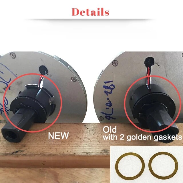
At 2:40 and 6:53 of this video there are 2 brass shims which my motor does not have. Are there different versions of this motor where some have these washers and others not?
 
Yes, that depends on torque sensor version. There are at least 2 versions. Old one needs 2 brass shims.
H54d93452083142db90f36857ef7707ff9.jpg_640x640Q90.jpg_.webp


2 torque sensor versions on Aliexpress
 
Last edited:
Thanks for that info falvick! But I have the old version torque sensor! The previous owner I got the broken motor from had to remove the torque sensor in order to add an extension (silver threaded piece) to fit motor onto a fat bike by tapping an internal thread in the housing. I wonder if the motor came w/o the 2 brass shims or if he inadvertently left them out during reassembly?
IMG_3300.jpeg

1709827905685.png
 
Per the previous owner, he does not recall encountering the brass washers so I will continue w/o them.
 
Has anyone noticed the outer ring of the transformer coil housing has a permanent magnet? A paper clip sticks to it. I'm guessing its purpose is to increase the efficiency of the transformer coils?

IMG_3304.jpeg
 
One surprise with the new casing is that it has an internal circlip, where the broken casing does not. The non drive side needle bearing has to be pressed in/out from the non drive side opening since it not machined for an interference fit all the way through. I am wondering why they added the circlip? Is it to act as a stop for the needle bearing so it does not walk? Has that been a problem on casings w/o the circlip?

The internal circlip complicates the job when it's time to replace the needle bearing. You need internal circlip pliers that can reach deep enough to remove the circlip first since it's blocking the needle bearing.

edit: You may be wondering about the small shiny ball at 10 o'clock on the shaft. It's a magnet that was inadvertently stuck to it.
IMG_3281.jpeg

IMG_3301.jpeg
 
Last edited:
Swapped the motor over. Is the OEM white grease compatible to the red Mobilith SHC 100 (which feels a little thicker)? I didn't want to clean off the virgin white grease (if incompatible) so I just scraped it off and transferred it over.

IMG_3315.jpeg

IMG_3321.jpeg
 
Take a look at this video. The in and out play of the main gear is excessive IMO. I hit the end of the torque assembly pretty hard multiple times with the rubber mallet but that's as far as it will go. I think the needle bearing (the captive one) on the torque sensor assembly did not go far enough into the casing. Do I need to hit it harder? Use a bigger mallet? Maybe use a hammer instead?

 
In my experience, there is always a bit of play, but yours looks a bit unusual.
However, I think it does not matter - and I would NOT hammer any further (there is no room to drive it further in.

Also, I think this play will be reduced once you have installed the axle and secured that with the circlips on both sides.
If too much play remains you can adjust that by adding shims underneath the circlips
 
With the screws tightened down on the plastic main gear cover, it does not lay flat against the casing. Free wheel drag is also increased. I think the torgue sensor assembly needs to go in further so the x-seal is not compressed so much as to buckle the cover, increasing friction.

I was holding the casing in my left hand while striking the mallet with my right. I think I need to support the casing on the ground and strike to eliminate the "give".
 
Good luck. In the video It looked to me that the 2 gears are flush / on equal height - thats why I thought it is pressed in to the max. If that is not the case, then maybe you still have some room. But be careful - also the ferrite coils underneath are very brittle and can be destroyed easily when hammering that gear down.
 
I just hammered it in (protecting all surfaces) with casing on firm concrete and it went in further. Plastic cover sits flush now with much less drag when turning the axle. Torque sensor assembly is fully supported by the non drive side needle bearing.

IMG_3339.jpeg
 
Next will be installing the controller and the type K temperature probe. I am light in weight plus there are no steep hills to climb around here. I will not be adding any type of cooling mods for now and will run it stock first. This digital thermocouple meter reacts pretty fast and is accurate enough.

 
Good luck. In the video It looked to me that the 2 gears are flush / on equal height - thats why I thought it is pressed in to the max. If that is not the case, then maybe you still have some room. But be careful - also the ferrite coils underneath are very brittle and can be destroyed easily when hammering that gear down.
I hope the ferrite coils will be ok from the hammering. Guess I will find out if the motor runs or not when installed on the bike. Main gear play is reduced and the cover sits flush now.

 
Interesting! Can you post a link to that discussion?
the magnets in the coil housing are pas sensor magnets, they are read by the black pas sensor that pokes through the hole in the casing from the controller. The power for the torque sensor comes from the controller.

i've spent more time than I should have working out how it works :)

 
the magnets in the coil housing are pas sensor magnets, they are read by the black pas sensor that pokes through the hole in the casing from the controller. The power for the torque sensor comes from the controller.

i've spent more time than I should have working out how it works :)


I have been following your post but missed the part where you talked about the PAS sensor only works with 5V.

I had no idea that there is a PAS sensor hidden in the TSDZ2 controller! How is it used to control the motor? There are very few discussions about it on the forum. I found these 2 posts on it:

TSDZ2 PAS sensor failure and adjustment (where it mentions there are 20 small magnets in the ring)

There are 16 or 20 - tbh I can't remember how many, would need to check the source code - magnets in the torque sensor coil ring.

Those magnets pass by the two hall sensors in the PAS sensor that is the small black lump poking out of the side of the motor controller. One hall sensor is out of phase from the other - so that pedal direction as well as speed can be determined.
pas sensor.png
How it's used to control the motor is a big question - depends on the firmware and what settings you're using. Only way to answer that completely is to look at the source code for the firmware in question. It's the ebike_app.c module in casainho's fw that does the control - see link:

TSDZ2-Smart-EBike/src/ebike_app.c at 9f8476fc2917b8282b320f1749b8a508f5e8d42e · OpenSourceEBike/TSDZ2-Smart-EBike
 
There are 16 or 20 - tbh I can't remember how many, would need to check the source code - magnets in the torque sensor coil ring.

Those magnets pass by the two hall sensors in the PAS sensor that is the small black lump poking out of the side of the motor controller. One hall sensor is out of phase from the other - so that pedal direction as well as speed can be determined.
View attachment 349144
How it's used to control the motor is a big question - depends on the firmware and what settings you're using. Only way to answer that completely is to look at the source code for the firmware in question. It's the ebike_app.c module in casainho's fw that does the control - see link:

TSDZ2-Smart-EBike/src/ebike_app.c at 9f8476fc2917b8282b320f1749b8a508f5e8d42e · OpenSourceEBike/TSDZ2-Smart-EBike
Thanks for the info! I'm not very good at following source codes and will have to rely on your's and other's expertise.
 
The motor is all back together but there is one M4 x 6 Allen head screw left over (2.5 mm allen key). Anyone know where it goes? I am hoping it's not mechanically critical and can be left out for now.

IMG_3353.jpeg
 
Running off a 48V battery from my Arrow 9 ebike. There was initially some uneven light clunking noise, which has gone away. Too bad I didn't capture it on video.

This is a KT LCD3 controller with V 0.18.2 OSF which I have no idea how to navigate ATM. Why is it running at the same RPM? Shouldn't RPM vary with throttle position? What other tests can I do on the bench before install on the recipient bike?

 
The motor is all back together but there is one M4 x 6 Allen head screw left over (2.5 mm allen key). Anyone know where it goes? I am hoping it's not mechanically critical and can be left out for now.

View attachment 349153
That looks to be one of the four around the plastic cover over the large and small internal cogs behind the chainring.
 
That looks to be one of the four around the plastic cover over the large and small internal cogs behind the chainring.
Those 4 plastic cover allen head bolts were missing. The cover was held on with 4 sets of Phillips SAE through bolts/ nuts. This lone M4 x 6 bolt is too short for the cover. Maybe it does not belong to this motor?
 
Last edited:
Back
Top