Controller with LCD panel hack

Modbikemax

1 kW
Joined
Jul 15, 2014
Messages
453
Location
Perth Western Australia
A friend asked me to attempt a repair on an "easymax easy bike".
It has an LCD panel with only pedal assist and no throttle.
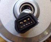
The interesting thing is that only one hall sensor is connected and that goes to the LCD panel.
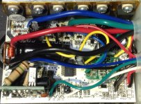
The controller has a small sub board with an IC that has the hall wires coming off this board to the main PCB.
I am guessing this sub board simulates the hall signals.
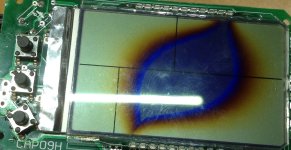
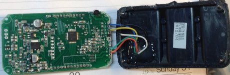
As you can see from the pics the LCD panel is toast.
What I want to do is remove the LCD and substitute it with an on off switch. Blue wire powers up the controller.
From what I can guess the single hall pulses turns the controller on when the front wheel motor is spinning for safety.
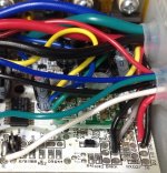
There are 2 wires, green going to "ZF" and white going to "IL" on the controller board.
Has anyone got any ideas on how to hack this controller? I think the green and white wires are the clue.
 

Attachments

  • image.jpg
    image.jpg
    174.2 KB · Views: 2,221
  • image.jpg
    image.jpg
    189.4 KB · Views: 2,221
  • image.jpg
    image.jpg
    206.5 KB · Views: 2,221
What you're saying doesn't make sense. I've never heardof or seen any LSW controller working like that. Maybe someone wrongly rewired something that made the LCD blow. Show us photos of all the connectors on the LCD and controller, so that we can see what you've got.
 
Looks like the LCd got cracked. :(

Seems to be a lot like my Fusin kit's controller, though it has more modes than yours.

https://endless-sphere.com/forums/viewtopic.php?p=584366#p584366

You might want to check for wires that carry battery voltage to the LCD; probably one of them will connect to another wire that has no voltage but is not connected to ground, and connecting these two together will then power up the controller.

BUT: don';t randomly connectc stuff or you will blow the controller up.

Also, the controller may not operate as it used to without the LCD to tell it stuff.
 
d8veh said:
What you're saying doesn't make sense. I've never heardof or seen any LSW controller working like that. Maybe someone wrongly rewired something that made the LCD blow. Show us photos of all the connectors on the LCD and controller, so that we can see what you've got.
The LCD was dropped and damaged not by incorrect wiring note the broken screen.
It is unusual that's why I'm asking.
 
amberwolf said:
Looks like the LCd got cracked. :(

Seems to be a lot like my Fusin kit's controller, though it has more modes than yours.

https://endless-sphere.com/forums/viewtopic.php?p=584366#p584366

You might want to check for wires that carry battery voltage to the LCD; probably one of them will connect to another wire that has no voltage but is not connected to ground, and connecting these two together will then power up the controller.

BUT: don';t randomly connectc stuff or you will blow the controller up.

Also, the controller may not operate as it used to without the LCD to tell it stuff.

The wires to the LCD carry + red and - black battery power, blue powers up the controller that much I have been able to work out. The "ZF" and "IL" are the two connections I am not sure of. I might try a 10k resistor high and low to see if it has any affect. These LCD style interfaces are quite common now so it would be useful to find out how they work.

In the end I may suggest to my friend to replace the controller with a more conventional ($30) one and use a twist throttle just to get the bike back on the road.
 
Here is a better picture of the controller. Note the small sub board on the right with the 3 hall wires coming out green, yellow and blue and no hall wires from the motor.
The blue wire powers up the sub board on the left which is a small voltage regulator feeding 12v to the rest of the controller.

Note the ZF and IL connections which come from the LCD panel. I suspect these enable the pedal assist.
 

Attachments

  • image.jpg
    image.jpg
    217.3 KB · Views: 2,186
Here is the back of the LCD, as you can see it has sustained further damage getting it apart (not by me).
Some wires have broken off. Note the blue wire comes off that large transistor which powers up the controller.
The white wire probably came off pin "D".
The yellow wire comes from one of the hall wires in the motor.
The Black wire probably came off pin "G"

My guess is the hall input (Yellow) gives the LCD processor pulse inputs to determine speed and to enable the controller once the bike is moving to prevent the motor engaging, if for example you are oiling your chain or moving the cranks, as a safety measure. Remember this bike only has pedal assist no throttle.

Thanks for any ideas.
 

Attachments

  • image.jpg
    image.jpg
    132.2 KB · Views: 2,178
LCD's (those posted about here on ES with any detail, anyway) are usually 5 wires:

battery +
battery -
controller power + (keyswitch/ignition)
serial data in
serial data out

That's how that Fusin kit I posted works, and it looks very much like what you have there. Including the hall-emulator to make it a sensorless controller, and the small SMPS board for LVPS (makes 12v and 5v from main battery power, though the latter is in a slightly different place).


If it's something other than that; it'll take the detective work you've started :) to figure it out. I'm curious to see how this goes.
 
It would appear that simply changing the controller for one with a twist throttle is not as simple as it first seems.
The motor has no hall sensors to detect phase angle even though the cables are there. There is a single hall sensor picking up a pulse once per revolution from a small magnet on the cover plate. To fit a twist throttle to this bike will require a new hub motor.
 

Attachments

  • image.jpg
    image.jpg
    219.9 KB · Views: 2,069
  • image.jpg
    image.jpg
    105.2 KB · Views: 2,069
  • image.jpg
    image.jpg
    47 KB · Views: 2,069
Modbikemax said:
To fit a twist throttle to this bike will require a new hub motor.
No, you just need a sensorless controller (or one that does both, etiher automatically or via jumper wire). Lots of them already do both.

(some controllers that have hall wires don't actually use them--both the XCM806 based ones I have on the SB Cruiser are like that--they ONLY work sensorless, even though they ahve the wires and are hooked up to the motors correctly, etc).


Or you can add halls to the motor, gluing htem in and connecting the wires to the plug. There is a currently active thread on how to do that. :)
 
You have an ordinary brushless sensorless controller. The motor has a speed sensor in it, which provides the signal for the speed display.

This one will work. You need to choose a LCD/LED panel to go with it. You can use the signal from your speed sensor or get the optional wheel-speed sensor.

https://bmsbattery.com/ebike-kit/545-s06p-250w-torque-simulation-square-wave-controller-ebike-kit.html?search_query=s06p&results=30

Your present controller might work if you short two wires: the battery positive that powers the LCD and the one from the LCD's mosfet that powers the controller. The problem is that you have no way of setting the PAS level because that is sent to the controller by data. You'll probably get the default level that you see when you switched the LCD on.
 
Back
Top