doublejosh
100 µW
- Joined
- Dec 20, 2015
- Messages
- 7
I'm trying to control a brushless hub motor via Arduino by way of the motor controller's throttle signal. Getting no spin 
To troubleshoot and calibrate I output a signal from the Arduino between 0v-5v to the throttle signal wire (green,vs red/white). I've tried voltages all over the range. I've even tried a slow oscillation between low and high to find the throttle control range (and eventually fine tune speed adjustment). No amount worked. The throttle does not affect the motor at all
It's worth noting that normally Arduino signal out is digital (using PWM to determine the voltage). But I'm using a DAC (digital to analog converter) to create what I think the throttle expects.
Troubleshooting... I can confirm the motor runs fine by using the self-learn wires. I'm able to make the wheel spin both ways (disconnecting/reconnecting). This strongly suggests the hub motor wiring (phase + hall) is correct.
My assumption is that normal throttles work by power flowing from the positive throttle output into the ground wire. Then normally a physical mechanism adjusts how much power it sends off to the signal wire instead. True?
Am I skipping a key electric loop that makes the throttle work? ...rather than just an amount coming into the signal wire? (I'm more software than electrical)
Perhaps there's a brake wire that's disabling the motor or some anti-theft feature locking the throttle?
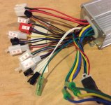
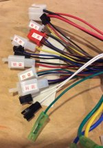
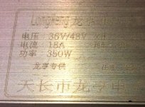
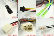
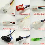
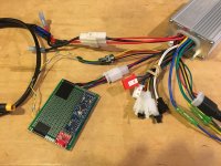
Pictures of the controller...
https://www.dropbox.com/s/3e4iu6j8uim939a/2016-10-02%2014.19.57.jpg?dl=0
https://www.dropbox.com/s/jroxhechn14w8rd/2016-10-02%2014.20.12.jpg?dl=0
https://www.dropbox.com/s/enp6b5w84i94099/2016-10-02%2014.22.00.jpg?dl=0
Background info...
Equipment:
- Brushless hub motor, 36v 500w
- Motor controller
- Arduino, 5v control signal output
- DAC (digital to analog converter, creates analog signal)
- Accelerometer (tilt sensor)
This is an effort to make an open-source, DIY, one-wheel, self-balancing, electric skateboard for myself and others. Hope you're into the idea!
https://github.com/doublejosh/emmett
https://github.com/doublejosh/emmett/wiki
http://openemmett.tumblr.com
To troubleshoot and calibrate I output a signal from the Arduino between 0v-5v to the throttle signal wire (green,vs red/white). I've tried voltages all over the range. I've even tried a slow oscillation between low and high to find the throttle control range (and eventually fine tune speed adjustment). No amount worked. The throttle does not affect the motor at all
It's worth noting that normally Arduino signal out is digital (using PWM to determine the voltage). But I'm using a DAC (digital to analog converter) to create what I think the throttle expects.
Troubleshooting... I can confirm the motor runs fine by using the self-learn wires. I'm able to make the wheel spin both ways (disconnecting/reconnecting). This strongly suggests the hub motor wiring (phase + hall) is correct.
My assumption is that normal throttles work by power flowing from the positive throttle output into the ground wire. Then normally a physical mechanism adjusts how much power it sends off to the signal wire instead. True?
Am I skipping a key electric loop that makes the throttle work? ...rather than just an amount coming into the signal wire? (I'm more software than electrical)
Perhaps there's a brake wire that's disabling the motor or some anti-theft feature locking the throttle?
Pictures of the controller...
https://www.dropbox.com/s/3e4iu6j8uim939a/2016-10-02%2014.19.57.jpg?dl=0
https://www.dropbox.com/s/jroxhechn14w8rd/2016-10-02%2014.20.12.jpg?dl=0
https://www.dropbox.com/s/enp6b5w84i94099/2016-10-02%2014.22.00.jpg?dl=0
Background info...
Equipment:
- Brushless hub motor, 36v 500w
- Motor controller
- Arduino, 5v control signal output
- DAC (digital to analog converter, creates analog signal)
- Accelerometer (tilt sensor)
This is an effort to make an open-source, DIY, one-wheel, self-balancing, electric skateboard for myself and others. Hope you're into the idea!
https://github.com/doublejosh/emmett
https://github.com/doublejosh/emmett/wiki
http://openemmett.tumblr.com