Converting B'twin Bike to Electric

flat tire said:
ningaman151 said:
cc/cv arduino

Brilliant plan except there are already a bunch of powerful, inexpensive, off the shelf boost / buck converters that do cc/cv mode..

Silly me, I've already bought a couple of these cc/cv buck converters. I used to just use them as regular buck converters :lol: . I will test them out once I get hold of them again!

So I'll need one for each battery, thats around 51 (17s3p) or 42 (14s3p) of them. So is it really this simple? Just have a ton on connections between the batteries and the buck converters and connect it up to charge and disconnect the charger and that's it? No extra circuitry required? (Other than say an Arduino hooked up to a display to show the charge progress etc.)
 
You only need one charger per parallel bank and you'll need to make sure they're isolated if you want to operate more than one at once.

Where the hell are you studying engineering?
 
ningaman151 said:
I don't know why you keep dumbing me down, I'm a final year electronic engineering student like I said, I've used op amps and other electrical components strenuously. I've also done some other electronics projects such as a drone, a buck boost converter, a near field card reader (done on pcb) and other projects that require good knowledge of electronics. So in terms of electronics I have a good ground, no need to relearn what I already know.
Not trying to "dumb you down". There've been several examples of your posts that don't show your education or experience (which you hadn't said anything about, making it impossible for us to know), so I each time had to make a choice between replying to the knowledge already shown, or assuming you knew exactly what you are doing and just letting you run with it and make pretty severe mistakes.

We get lots of people here new to ebikes that know something about electronics, but not much, that post the same way you do, even having done other electrical and electronics projects before, but still making mistakes that they wouldn't if they were to look up the spec sheets and/or principles for some of the parts they use, and if I assumed they knew what they were doing and let them go, they wouldn't end up with a working project (at least not without a lot of frustration and failed components, or at least things that simply won't work together, either at all, or the way they want them to).

More than a few people come here wanting to design their own controllers, motors, chargers, batteries, etc., but they don't know anything about any of it...and may post the same way you have, not giving us any of their experience level, and if we assume they know everything they need to, without telling them what they're going to need to learn, they aren't going to be able to complete their project, and they won't even find out they need to know these things until "too late" (too far in, too much spent, not enough time left, etc).

So I find it's better to assume someone that doesn't say or show their knowledge or experience level that they dont' have any, and help them more, rather than assuming they knwo everything already, and give them only very basic answers that probably wont' help htem.

So based on my prior experiences with a decade of learning and helping out here, and my own decades-old electronics technician degree, I replied to you based on what I saw.

Now that I know you're experienced at all this stuff, I can assume you know what you're doing and only answer the direct questions you have, and avoid explaining stuff you already know without correcting you.
 
flat tire said:
You only need one charger per parallel bank and you'll need to make sure they're isolated if you want to operate more than one at once.

And the balancing automatically takes place?
By isolating do you mean connecting each parallel bank's positive and negative end to the buck converter's positive and negative end? And using the negative end of each bank as the ground of their buck converter? Will this be fine with all the banks still being connected to each other? Or will I need to disconnect them?

Where the hell are you studying engineering?

At the University of Southampton, in the UK.
 
amberwolf said:
Not trying to "dumb you down". There've been several examples of your posts that don't show your ...

Don't worry about it, let's just leave it behind us and let's focus on making ebikes :D. Yeah sorry sometimes I get a little lazy or rush and I miss important details :lol:.

Yeah so now we're at the point of using off the shelf buck converter with cc cv capability (from AliExpress) to charge my li ions. I think I have one of these modules at home, I'll test them out both in setup and also try charging a single li ion and a chain of series of 2s1p li ions with it while monitoring. I'll report back with the results.

However, one thing I'm not sure about is how to charge li ions in a parallel and series chain. A previous reply suggested I charge an entire parallel block using a single charger.

How would isolation work? Just use the battery's negative terminal as ground for the buck converter for one block? And charge while all the parallel blocks are connected?
 
Please, for the safety of whatever industry you would enter, DO NOT BECOME AN ENGINEER.
 
flat tire said:
Please, for the safety of whatever industry you would enter, DO NOT BECOME AN ENGINEER.

How about being clear and thorough instead of throwing insults like a child? I haven't burned anything yet, because I'm still asking about how to do things correctly so that nothing goes wrong (minimise the amount of times things go wrong) when I do my build. I could have just started building anything and lit up a house fire. But instead I'm doing the safe thing of asking for help with my project.

Your replies so far have been so ambiguous and non-detailed I wonder why you even took the time to write them. It doesn't hurt to include a few more sentences that further explain the points you're trying to get across. Thank you. :|
 
ningaman151 said:
However, one thing I'm not sure about is how to charge li ions in a parallel and series chain.
There are two basic ways: Bulk charging, which is connecting the charger across the whole seriesed set of cells.

Single-cell charging, sometimes called Balance charging, which is connecting each charger across just one parallel group of cells.

Variations on those you can look around at various battery pack build and charging threads to get the details; there's a lot of DIY charging / balancing scheme threads.


How would isolation work? Just use the battery's negative terminal as ground for the buck converter for one block? And charge while all the parallel blocks are connected?

The entire battery would be built just as normal, and connected in however many series and parallel cells for the whole pack configuration you' need. You'd just leave "balance wires" connected to every series interconnect between parallel groups, plus one at the main positive and negative connection points, just as if you were going to have a BMS.

Then you can wire your set of single cell chargers in series, and connect it up to those balance wires.

Isolation is just like any other circuit that has different voltage potentials and different grounds--one side can't be connected to the other, like in an SMPS.


Not meant to be rude, but I'm curious: This is fairly basic electrical and electronics stuff we covered back in the 1980s when I went to tech school, so I'm not sure why they don't teach it in current engineering classes?
 
amberwolf said:
ningaman151 said:
However, one thing I'm not sure about is how to charge li ions in a parallel and series chain.
There are two basic ways: Bulk charging, which is connecting the charger across the whole seriesed set of cells.

Single-cell charging, sometimes called Balance charging, which is connecting each charger across just one parallel group of cells.

Variations on those you can look around at various battery pack build and charging threads to get the details; there's a lot of DIY charging / balancing scheme threads.


How would isolation work? Just use the battery's negative terminal as ground for the buck converter for one block? And charge while all the parallel blocks are connected?

The entire battery would be built just as normal, and connected in however many series and parallel cells for the whole pack configuration you' need. You'd just leave "balance wires" connected to every series interconnect between parallel groups, plus one at the main positive and negative connection points, just as if you were going to have a BMS.

Then you can wire your set of single cell chargers in series, and connect it up to those balance wires.

Isolation is just like any other circuit that has different voltage potentials and different grounds--one side can't be connected to the other, like in an SMPS.

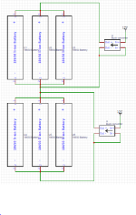
Capture.PNG

So is this one way to do the charging? This configuration would be balance charging from what you're saying? The battery in this schematic is a 2s3p battery.


Not meant to be rude, but I'm curious: This is fairly basic electrical and electronics stuff we covered back in the 1980s when I went to tech school, so I'm not sure why they don't teach it in current engineering classes?

They teach much more advanced theoretical stuff at engineering at university. This is more basic and practical, and is expected of the students to do their own research to learn.
 
www.recumbents.com said:
yes, your drawing is correct, assuming that the buck converters are all properly isolated.

Warren.

What do you mean by properly isolated? As in using different 12V supplies? Because in the image the 12V supplies are the same.
 
As you noted you are sharing a 12V power supply between all of the buck converters. This means that all the input + and - are tied together. If, as shown in your drawing the - side of the output is ties to the - side of the input, this will mean that all the - side outputs are shorted together which will effectively short out each parallel array of batteries. Probably not what you had in mind.

You need to ensure that the outputs of the buck converters are isolated from the inputs to prevent this shorting issue.
 
www.recumbents.com said:
As you noted you are sharing a 12V power supply between all of the buck converters. This means that all the input + and - are tied together. If, as shown in your drawing the - side of the output is ties to the - side of the input, this will mean that all the - side outputs are shorted together which will effectively short out each parallel array of batteries. Probably not what you had in mind.

You need to ensure that the outputs of the buck converters are isolated from the inputs to prevent this shorting issue.
I think I get what you mean, but I'm not sure what to do about it.

I'm using a desktop power supply as my power supply. I'll be using the 12V rail to supply power to the charger. What would I do in this situation to isolate the buck converters. I want to keep using a single desktop power supply's 12V rail as the power source. Thanks!
 
www.recumbents.com said:
At the very least, don't tie the input [-] to the output [-] !

You should be able to read the Buck converters technical specs to see if they are isolated.

The input and output (-)s are shorted together anyways. The term isolated keeps being thrown around without me actually knowing what it really means. Can you please provide an explanation? These buck converters are Chinese I doubt there are datasheet for them. (Other than the chips)
 
www.recumbents.com said:
If either input and output are shorted together it won't work. That means it's not isolated. Do you understand why that is a problem?

Just google "isolated buck converter" for an explanation.

I'm sorry, I don't understand why that's a problem, can you please explain? From the schematic I posted previously I can't see where it is shorted.

I googled it and I haven't found any useful results. :oops:
 
E-HP said:
I'm very confident that you can figure it out.

Not sure if you'll encounter this in the future, but I was just talking to one of my engineers yesterday, because we're getting ready to interview candidates next week. He always throws in a random picture or schematics like this to ask, "describe what you see?", or "what's wrong with this picture?", and gives them a minute to study it. Some know; some don't know and problem solve on the spot (this provides the most insights); some just give up. He says I never see the last category, since he's already weeded them out.

What's the point of all this? You could have easily provided an explanation instead of making me search for an hour or so. I don't even understand why you're making posts like this.

If you are going to take the time to post a reply, you might aswell make it helpful, instead of being smug, which doesn't help anyone. Thank you :D
 
ningaman151 said:
E-HP said:
Point taken.

So, could you please explain to me what's wrong with my schematic? The buck converters are not grounded by the way.

www.recumbents.com explained the problem 11 posts up. trace your common negative. either two power supplies, the fly-buck circuit www.recumbents.com is referring to, or redesign the circuit are possible options.
 
Back
Top