
You are using an out of date browser. It may not display this or other websites correctly.
You should upgrade or use an alternative browser.
You should upgrade or use an alternative browser.
Crystalyte Controllers - Repair and Modification information
- Thread starter fechter
- Start date
If you're real good, you can suck the leg right out of the hole. Usually it's not that easy.
Plan B:
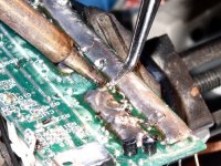
Use a tweezers and hold the leg while heating with the iron.
DO NOT pull very hard or the traces will lift off the board (bad).
Apply heat and wait for the leg to become loose and it will pull out very easily. Try to touch the iron directly to the piece of leg sticking out, this will heat the leg, not the board.
Plan B:
Use a tweezers and hold the leg while heating with the iron.
DO NOT pull very hard or the traces will lift off the board (bad).
Apply heat and wait for the leg to become loose and it will pull out very easily. Try to touch the iron directly to the piece of leg sticking out, this will heat the leg, not the board.
Attachments
Once the leg pulls out, the hole usually fills in with solder.
You can attempt to solder suck again. Putting the sucker on one side and the iron on the other side works well if you can manage to hold the board still (this is tricky).
Plan C:
Solder wick. Solder wick is great for beginners. The idea is to get the wick pinched beteween the tip of the iron and the hole you're trying to clear. Good heat transfer is important. A small bead of solder on the iron helps get the process started. Just press the solder wick down with the tip of the iron and watch to see when the solder wicks up.
If it doesn't seem to be doing it, try it from the other side.
Remember your 10 - 15 second time limit.
Attachments
Repeat
Repeat
Repeat
Repeat....
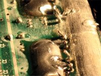
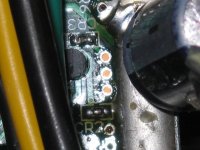
Until the holes are all clear. Use a light behind the board and look through the holes. The hole needs to be clear enough to pass the leg on the new part.
The holes should look like this:
Repeat
Repeat
Repeat....
Until the holes are all clear. Use a light behind the board and look through the holes. The hole needs to be clear enough to pass the leg on the new part.
The holes should look like this:
Attachments
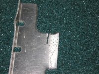
At this point, closely examine the board for small solder balls that might have spewed out during the desoldering process.
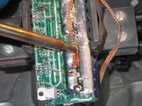
If you are interested in adding extra copper to the buss bars, now is the time. Lowell used heavy solder wick braid, which should work great. I think this would only be a consideration if you wanted to try running over 70 amps or so.
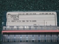
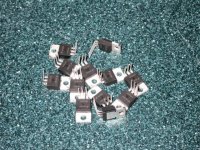
Next, we need to prepare the new FETs.
If we look at one of the stock FETs, you'll see the legs are bent 90 degrees a certain distance away from the case. We want our new FETs to be bent the same way.
If you are interested in adding extra copper to the buss bars, now is the time. Lowell used heavy solder wick braid, which should work great. I think this would only be a consideration if you wanted to try running over 70 amps or so.
Next, we need to prepare the new FETs.
If we look at one of the stock FETs, you'll see the legs are bent 90 degrees a certain distance away from the case. We want our new FETs to be bent the same way.
Attachments
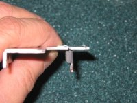
I made a bending jig from a piece of scrap aluminum with a slot sawed in it with a hacksaw.
The new FET legs are inserted in the slot and bent over flat.
It's important to avoid bending the legs right where they go into the case; it's easy to break them off that way.
The new FET legs are inserted in the slot and bent over flat.
It's important to avoid bending the legs right where they go into the case; it's easy to break them off that way.
Attachments
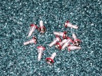
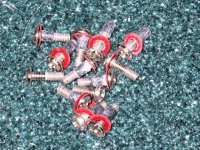
After bending all the FETs, it's time to upgrade the screw insulators.
I removed the stock heatshrink and replaced it with thicker tubing.
Alternately, you could buy some factory made insulating washers.
I removed the stock heatshrink and replaced it with thicker tubing.
Alternately, you could buy some factory made insulating washers.
Attachments
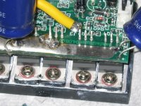
Next, time to stuff the new FETs into those holes that were so hard to clear out. The legs should go in easily. If a hole is partially blocked, don't force the leg in, as it might bend over or tear the land off the back of the board. It's fair to use the tip of a safety pin or tiny screw driver to open up the hole a bit
Next, and I see some people missed this step, is to attach the heatsink with the insulated screws.
Remember, the voltage regulator screw needs to go in first, then the FET screws.
The reason I like to do this is to perfectly align all the FETs before soldering. We'll take the screws back out later, so don't put them in too tight.
If the legs aren't aligned properly and you solder them in, there's the risk they might break off when you force them into position.
Attachments
Now, time to fire up the soldering iron again.
The legs that go to the buss bar should be soldered from the buss bar side. You can't get enough heat/solder to flow through the board to do them from from the other side.
Solder these first, along with the gate legs (the right hand leg on each FET from this angle).
To get access to the legs, it will be necessary to bend the capacitor leads. Avoid bending them as much as possible to avoid breakage.
If you're a newbie, it might be helpful to put a small dab of paste flux on the legs before soldering. It's kind of messy, but helps the solder flow.
Attachments

Once all the legs are soldered on this side, take out all the screws again and turn the board over.
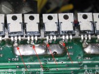
Same deal, solder the legs that go to the buss bars.
Hold the iron so it contacts both the leg and the trace on the board. Feed quite a bit of solder into the intersection, then drag the tip up the leg to prevent bridging the legs.
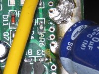
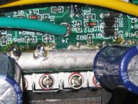
If you are installing higher current FETs, like IRFB4310's or 4110's, and want the current limit to be higher, now is the time to beef up the shunt.
The shunt is four parallel wires made of a special resistor material.
To increase the current limit, I filled the space between two adjacent wires with solder. Depending on the amount of solder added, this usually works out to 60-80 amps.
Same deal, solder the legs that go to the buss bars.
Hold the iron so it contacts both the leg and the trace on the board. Feed quite a bit of solder into the intersection, then drag the tip up the leg to prevent bridging the legs.
If you are installing higher current FETs, like IRFB4310's or 4110's, and want the current limit to be higher, now is the time to beef up the shunt.
The shunt is four parallel wires made of a special resistor material.
To increase the current limit, I filled the space between two adjacent wires with solder. Depending on the amount of solder added, this usually works out to 60-80 amps.
Attachments
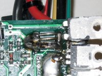
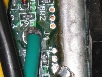
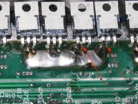
Some of the legs go to the positive buss, which is under the FET body.
For these, I tin the tip and heat the leg, while feeding solder to the opposite side of the leg. This means the solder comes in through the space between the FET body and the board. Lift the FET body slightly to get access if necessary.
For these, I tin the tip and heat the leg, while feeding solder to the opposite side of the leg. This means the solder comes in through the space between the FET body and the board. Lift the FET body slightly to get access if necessary.
Attachments
Once all the legs are soldered, do a careful visual inspection of the joints. Look for solder balls or bridged spots that would short something.
It doesn't hurt to clean off the flux residue from around the legs. I use rubbing alcohol and an old toothbrush, but alcohol does not dissolve the flux very well. There are special flux cleaners available. I also use a small screwdriver tip to scrape the flux out of the space between traces.
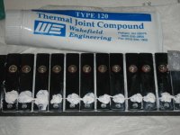
Once it's all cleaned up, time to goop up the heatsink with some fresh compound.
Alternately, you could go out and buy some heatsink pads, but I think the goop works fine.
It doesn't hurt to clean off the flux residue from around the legs. I use rubbing alcohol and an old toothbrush, but alcohol does not dissolve the flux very well. There are special flux cleaners available. I also use a small screwdriver tip to scrape the flux out of the space between traces.
Once it's all cleaned up, time to goop up the heatsink with some fresh compound.
Alternately, you could go out and buy some heatsink pads, but I think the goop works fine.
Attachments
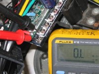
Next, test for shorts in the insulators. Use an ohmmeter and measure between any screw head and each FET tab. The reading might bounce around a bit, but should be OL or at least higher than 10k ohms. Anything that looks lower than 10K should be checked out.
Attachments
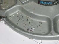
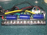
Now we can glue the capacitors back down to prevent vibration failures.
This particular one used hot melt glue for this. Somehow, using hot melt glue on something that gets hot seems like a bad idea.
I prefer silicone RTV glue, since it won't melt and has good thermal conductivity.
Make sure to let the RTV dry for 24 hours before closing up the case or the vapor from curing might cause corrosion on the board.
Here's the caps glued down:
Attachments
Now just re-install all the screws and reconnect the reverse wires if you want to retain this feature.
When Things Go Bang - Troubleshooting 101
Now what happens if your controller dies and you can't get a replacement under warranty? First, make sure it's not dead.
There are a few simple tests that can narrow down the likely causes of failure.
Fechter's 1st rule of troubleshooting: Always check the thing that's easiest to fix first.
Loose wire connections are a frequent cause of failure. Finding them is not always easy. Check all the wires and connectors before ripping things apart.
That said, here are a few other tests you can do:
Does the red LED light up on the controller? If yes, then the voltage regulator and supply power to the controller is good. If no, suspect a problem between the batteries and the controller. Check the fuse and fuse holder. Measure the voltage across the battery input wires to the controller.
Do the "rollback" test. Turn on the controller (check that light is on) and try to push the bike (or scooter, whatever) backwards quickly, no throttle.
Turn off the power and repeat the test. If you get a strong resistance to rolling backward with the power on, then the hall sensors and low side FETs are working properly. There should be minimal resistance with the power off. If resistance is still present, check for shorted FETs. If the rollback test passes, but the motor still won't go, then suspect the throttle.
If the rollback test fails, check for shorted FETs and check the hall sensors.
To check for shorted FETs, disconnect the phase wires from the controller to the motor. Use an ohmmeter on low range (or autoranging) and measure from each phase wire to each power wire (6 combinations) and look for a low resistance. Any measurement that looks like less than a few ohms indicates a shorted FET. Normally, all the resistances should be in the megohm range, and may vary with time.
Attachments
If none of the FETs are shorted, that's a good sign.
Checking the Hall Sensors
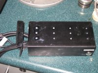
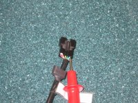
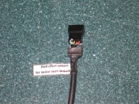
Another common problem is a broken hall sensor wire. To check the hall sensors, the motor and controller must be connected. Of course, this makes probing the connector pins difficult. The usual approch is to "back probe" the connectors. If there's heatshrink around the connector, you can carefully slide it back to expose the rear of the connector.
Put the negative meter probe to the battery negative. An alligator clip is handy here, since you need both hands to measure the hall connector.
If your meter probe is too fat to fit into the connector, you can take a short piece of solid wire and wrap it around the probe to make a "stinger".
With the mini DIN plugs, you can loosen the strain relief screws and unscrew the back of the plug body. Any heat shrink can be slid back just far enough to get access to the connector pins.
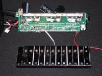
With the power on, but no throttle, measure each of the 5 hall wires.
Black and red from the controller are power. Black should read near zero, red should be around 12v (8-14v OK).
The green, yellow, and blue signal lines should have either a high or low output depending on motor position. Measure each one and slowly turn the motor. You should see each one toggle between high and low as the motor turns.
Note: this measurment is done with the motor connected, not show in the pictures below:
Checking the Hall Sensors
Another common problem is a broken hall sensor wire. To check the hall sensors, the motor and controller must be connected. Of course, this makes probing the connector pins difficult. The usual approch is to "back probe" the connectors. If there's heatshrink around the connector, you can carefully slide it back to expose the rear of the connector.
Put the negative meter probe to the battery negative. An alligator clip is handy here, since you need both hands to measure the hall connector.
If your meter probe is too fat to fit into the connector, you can take a short piece of solid wire and wrap it around the probe to make a "stinger".
With the mini DIN plugs, you can loosen the strain relief screws and unscrew the back of the plug body. Any heat shrink can be slid back just far enough to get access to the connector pins.
With the power on, but no throttle, measure each of the 5 hall wires.
Black and red from the controller are power. Black should read near zero, red should be around 12v (8-14v OK).
The green, yellow, and blue signal lines should have either a high or low output depending on motor position. Measure each one and slowly turn the motor. You should see each one toggle between high and low as the motor turns.
Note: this measurment is done with the motor connected, not show in the pictures below:
Attachments
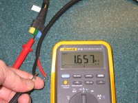
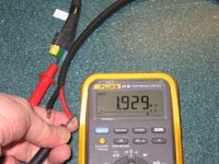
Checking the thottle is done in a similar way.
The throttle connector has 4 wires. Colors below are coming from the controller:
With power on, red should read around 5 volts.
Black should be near zero.
The white wire is the signal wire, and should vary from about one volt at zero throttle to about 4 volts at full throttle.
The purple wire will read battery voltage.
Colors may vary depending on model, but the measurements are the same. Measure all the wires if you don't know the colors.
I'm sure there's more, but I can't think of any at the moment.
ANY QUESTIONS?
ANY QUESTIONS?
CGameProgrammer
10 kW
Perhaps you should talk more about which replacement FETs to use. There are, after all, a few good choices.
Also, you might mention that heat dissipates from the case, particularly the bottom, and that there should be good airflow around the controller.
Also, you might mention that heat dissipates from the case, particularly the bottom, and that there should be good airflow around the controller.
Similar threads
- Replies
- 10
- Views
- 1,320
- Replies
- 128
- Views
- 12,521
- Replies
- 437
- Views
- 63,742
- Replies
- 444
- Views
- 105,943