Crystalyte Controllers - Repair and Modification information

CGameProgrammer said:
Perhaps you should talk more about which replacement FETs to use. There are, after all, a few good choices.

Also, you might mention that heat dissipates from the case, particularly the bottom, and that there should be good airflow around the controller.

You think there'd be any benefit to slapping on a heat sink on that side of the controller, especially if it's not sitting out in the wind but in a bag somewhere?
 
Having run the 4110 FETs with external heat sinks on the controller case for a while, I've taken them off due to not being necessary. The most amps I can pull for any length of time is about 50, and at that current each FET only has to dissipate about 2.3W.
 
With the 150v FETs, the on resistance will be much higher, so heating will be an issue, especially if the controller is mounted inside a box or something.

I got some small aluminum U channel and was thinking about mounting 3 strips of it under the 3 rows of heatsink screws to make fins. Any kind of heatsink with fins could be added.

If the screw side of the controller sits where the wind blows on it, heating should not be a big problem.

Somewhere back on page 1 or so, there's a Excel spreadsheet with most of the likely FET replacement candidates listed.
I'm not convinced that using 150v rated FETs is a good idea, but if you want to run over 100v, you need them. I prefer the lowest possible on resistance, since this reduces heating.

IRFB4110's are the best for 100v rating.
IRFB4310's are easier to find and cheaper. Slightly weaker than the 4110's. At least two people have tried them successfully.

If you only need a 75v rating, (60v system), then you could use a IRFB3077 or IRFB3808 (the ones I'm using on one controller).
 
AWSUM, ! ! !
MUCHO THANKO again fechter,

If possible I would like to see a more in-depth section "trouble shoooting" various test points their should be values, testing fets, (in depth) , testing hall sensors, throttle,
The correct resistance to add to LVC for various voltages to adjust the LVC

Did i miss a thread ?
what about the FDP 2532 same on resistance as stock but rated 150V 79 A
 
Hello

Must say a big big thanks to Richard for doing this thread!! he has spent a lot of time on it, this will save me from answering a lot of questions!

My controller mods basically were just as Richards, I like the idea of the Fet Bender and also the tip about loosely fitting them in the holes then lining them up then soldering them! this is a great Idea, I sort of lucked it! its so important though as side presure on a badly aligned fet is not good as it can break the legs and cause the leakage problem through to the case, so I will do that on the next one!

The 150V fets heat the same as the stock ones, and yes at 72V you need the screws facing the airflow to keep heating down, if you run 72V and have the controller in a bag it will quickly hit the overtemp limit on the controller and cut the power, this happens on the KMX I have to hang it outside the bag in a net to keep it cool when running 72V.

Thanks again Richard great workthough anyone with half decent soldering skills, good eyes and a steady hand should be able to follow this guide and bring back a controller back from the dead and make it better! Like the Bionic Man!! ha ha remember that show?

Cheers

Paul
 
29a said:
AWSUM, ! ! !
MUCHO THANKO again fechter,

If possible I would like to see a more in-depth section "trouble shoooting" various test points their should be values, testing fets, (in depth) , testing hall sensors, throttle,
The correct resistance to add to LVC for various voltages to adjust the LVC

Did i miss a thread ?
what about the FDP 2532 same on resistance as stock but rated 150V 79 A

Yes, I forgot some stuff. I'll try to add it later.

The FDP2532's seemed to be the best 150V rated ones that were available. These need to be run at the stock current limit. If you want to run a 120v battery, 4110's will likely blow up.
 
Here's an easy mod that improves the low speed throttle response.
The throttle output is a nominal 1 volt at zero throttle and 4 volts at full throttle. The controller, however, does not begin to produce output until the throttle voltage reaches 1.4v or so. This makes it necessary to move the throttle almost half way before the motor starts, and makes the throttle extremely sensitive in the remaining travel.

Most hall throttles have a non-linear output curve that is more gradual at the low end. This is supposed to make the response more manageable, but since the controller has such a high starting threshold, the gradual part doesn't get used.

To correct this, you can install a trimmer pot in series with the negative power lead (black wire) of the throttle. I used a 200 ohm, 20 turn pot.

With the wheel off the ground, the pot is adjusted until the motor just starts to move, then backed off a turn or so to make sure the motor stops.

With my throttle, the resistance at the proper adjustment was around 100 ohms.

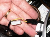
Here's a picutre of mine. Note: I'm using non-standard color coded wires.
 

Attachments

  • Throttle smoother.jpg
    Throttle smoother.jpg
    49.5 KB · Views: 6,512
Back to troubleshooting,

If the controller suffers from shorted FETs, or let a bunch of stinky smoke out, you'll need to replace FETs.

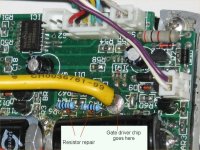
When the FETs blow, it almost always takes out the gate resistors. The gate resistors are tiny little 10 ohm chip resistors. They act as fuses when the FETs blow, protecting some of the downstream circuitry (sometimes).

When reparing a blown controller, always check the gate resistors. With a ohmmeter, measure across each resistor. They should read 10 ohms. A blown one will usually read several hundred ohms. Anything over 12 or so should be replaced.

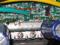
Replacing the chip resistors is no fun because they're so small. All the ones I found that were blown were essentially open, so I just left them in place and soldered a new 10 ohm resistor across them.
 

Attachments

  • Controller Repair 2.jpg
    Controller Repair 2.jpg
    76.9 KB · Views: 6,508
  • gate resistors.jpg
    gate resistors.jpg
    75.5 KB · Views: 6,496
If the gate resistors blew, there's a 50% or so chance that the gate driver chip or the two transistors on the high side drive also blew. These are difficult to test without connecting a motor.

In the absence of hall signals, the controller will not produce any output, so the only way to test is to connect a motor. If you want to probe the gate signals, you will have to power up the controller with the cover off and have the motor connected. This is a PITA. I found a tiny brushless motor that I use for bench testing, but the full sized motor will work.

Any faults in the hall signals or gate drives might result in shorts to the battery, so testing should be done with a current limited power supply. If you don't have a bench supply, use a small fuse (5 amp?) or something like a car headlight bulb in series with the battery to prevent overcurrent.

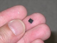
I replaced a blown gate driver chip by using solder wick and a razor blade to remove the old chip. Soldering tiny smd chips is challenging. I wrap a small piece of solid copper wire around the tip of my soldering iron to make a 'stinger' small enough to heat one leg at a time. After flowing the solder, drag the tip away from the chip, parallel to the legs to prevent bridging adjacent legs. If you bridge them badly, you'll need to use solderwick again to clean them.
 

Attachments

  • IR2101in hand.jpg
    IR2101in hand.jpg
    29.7 KB · Views: 6,465
Low Voltage Cutout

The low voltage cutout circuit is designed to fold back the current limit when the battery voltage drops below a predetermined level.

The circuit consists of a voltage divider, a diode, and the comparator built into the PWM chip. When the voltage at the junction of the diode and R6 reaches about 3.8v, the diode starts to conduct and pulls down the input to the comparator, reducing the PWM duty cycle.

The resistors that make up the divider were difficult to read on my controller, and I was too lazy to unsolder them to measure the values.
I swear one of them looks like 104, which would be 100K, but that value wouldn't work against the 5.1k to get the right cutoff voltage.

If you snipped the resistor that has the switch across it, and put a potentiometer where the switch is, you could make the LVC adjustable.
I don't have known tested values for this resistance, so could only guess at this point.
 
fechter said:
mod that improves the low speed throttle response

Keep in mind is the value will drift a little with temperature, so if it's ajusted spot on at 20, it may want to creep onward a little when it's -20.
 
On my conversion I was removing the fets (after six hours desoldering)and two of the solder pads came off with a fet,
Is it ok to just solder the new ones in the holes ( will they still make contact ) or do i have to run jumpers :?:
If the jumpers are ness could you let me know from where to where :?:
I'm sure this will be common so if you could post the ness info for all the fets pads/tracks.

Allso i'm not clear about where to add the extra copper for higher amperage to buss bars and which fet legs.
 
It depends on which pads came off. If the trace is solid on one side of the board, but the pad fell off on the opposite side, don't worry about it.

Each FET leg only connects on one side of the board or the other (not both sides).

If the gate trace comes off, you will most likely need a small jumper to the gate resistor.

If you study the photos, it should be possible to see how it went. Each of the 3 phase sections are pretty much identical, so you can look at the adjacent section.

The extra copper would go in the buss bar, which runs along the edge of the board, on both sides. Unless you're planning on running over 60 amps for extended periods of time, it might not be worth the effort.
 
just a heads up for those newbs like me,
The fets are static sensitive.
don't use the solder pump on the new fets if you bridge the legs, the static from plastic pump will trash them as i did
:cry: :(
 
Good point. San Francisco is typically so humid that static is not an issue, so I forget about that. They do make anti-static solder pumps.
Before touching a circuit board with tools or hands, touch the heatsink or a ground trace on the board first to dissipate static.

If you walk across a rug and touch the circuit in the middle somewhere, it's likely to get zapped.
 
So, what's this regarding a ramp-up delay, how can it be nuked?
 
There's a capacitor on the board that controls the ramp up. Stock is 10uf. If you replace it with a smaller one, like 1 uf, it will ramp up much quicker.

It might work to just remove it completely.
 
it could be interesting regarding about 0-100m acceleration time test :twisted:

the ka3525A chip look like a PWM controller very similar to the popular TL494 used in most PC psu and car audio amplifier H-V psu..

About the capacitor,, it is shown on the page 4 of the fairchild documenthttp://www.fairchildsemi.com/ds/KA/KA3525A.pdf

They call it "soft start" and is connected to the pin 8

but my question is:

By doing this, does the current limit circuit of the controller will be affected?

I would not to blow my controller... I just hope the limit will still protect the it...

Doc
 
Correct. It's a very common pwm chip.
Changing the soft start capacitor will not affect the current limit. That's done in a different part of the circuit.
 
been searching a little more for local components how would this work out as a replacement for IRF3205 Fets would a direct replacement work Current is only about half that of the originals but voltage is nearly twice
 

Attachments

  • FD-FDP3652.pdf
    263.3 KB · Views: 291
What controller uses those?

The FETs in the datasheet have a pretty high on resistance. You should try to find something with a lower resistance if you can.

The ones in my selection guide are by no means the only ones on the market. Even the dreaded IRFB4710's have a lower RDS.

Part - RDS(on) 10V (mOhms)
IRFB4110PBF - 4.5
IRFB4310 Discrete - 7.0
BUK7510-100B - 8.6
IRFB4410 Discrete - 10.0
IRFB4710 Discrete - 14.0
 
About my controller repair,

That will be a little bit harder than I expected.. I can only get 2/3 of the component for raisonable delay...

I wonder if someone have some in stock?

like the:

-UPC1246C
-HEF4073BP
and other components

-The amounth is around 120$.. and new 4110 fets
-A brand new controller with old 4710 is 190$...

Any suggestions?

Fechter, are you searching for some job to do :lol:

I would agree to give you my controller to repair it and mod it to the 4110 fets

How much would you charge me for that? (PM me)

Doc
 
Thanks Doc,
The animation is one that I had earlier, but the original website went away. This is a copy of it, so I added it to the "how motors work" thread.
 
Another Tip

I found then when testing between battery positive or negative on one of the phase banks on a good controller that worked I had a reading of 400K ohms or so, the other phases were 2-3 meg ohms, after contacting Richard (fechter) he advised me it was either gate leakage in a fet or solder flux.

Well i did some research and it does indeed seem solder flux can be conductive! there was a lot of it around the legs of the fets on this phase bank, I re soldered the fets legs and cleaned as much off as I could and now the reading is 1 meg ohm! much better.

I never new solder flux could conduct but it appears if its thick enough and there is enough of it that it can, something to check for and clean up if you spot too much of it on your controller.

Thanks to Richard for pointing this out.

Knoxie
 
Back
Top