Cycle analyst for high 100V motorcycle

JoeReal

10 mW
Joined
Feb 23, 2015
Messages
30
Hey guys,

I installed my Cycle Analyst V3 on my motorcycle yesterday and had a couple questions-

How did you install the speedometer? The magnet that attaches to the wheel is made for a spoke, not a rim... Any ideas?

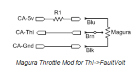
I am using a Magura throttle with a Kelly controller, am I able to pass the throttle through the CA? If so, what is the benefit?

Thanks for the help guys.

Here's a picture of the bike, because who doesn't like pictures of motorcycles?

b43c85c657c32aba2a9853b36c6f92a5.jpg
 
JoeReal said:
I don't really want a cycle analyst on my bike, I want to build my own...
I see that your plans have somewhat changed... :wink:

The manual answers the questions you have posed. Go to the Grin site to download a V3 manual - presently the [strike]Un[/strike]official User Guide. Also read the CA V3 product page in detail - it contains important information.

You may find this ES post of interest: CA V3 Kelly KBS Wiring in conjunction with "Appendix B. Add/Remove Wheel Speed Pickup Sensor".
EDIT - Hmm - okay, new facts posted below - HPM controller = no halls, so that ES post about Kelly KBS is not useful...
 
Scottydog said:
Leaf cells?

Cool! What's the specs on the bike?

Nice!

Yup, 12 leaf cells charged to 4.16v Max. So, 99.8v pack.

Motenergy ME1003 motor

Kelly HPM 120V 600A controller set to max.

3.15:1 gear ratio

78mph max speed

0-60 8.0s (Removed 8.3s, just hit 8 flat)


Thanks!
 
teklektik said:
I see that your plans have somewhat changed... :wink:

Ha, you got me. I WAS planning on making my own. buuuut full time school and full time work said no. So how could I say no to this system, especially at that price :lol: Maybe when schools done :D

teklektik said:
The manual answers the questions you have posed. Go to the Grin site to download a V3 manual - presently the [strike]Un[/strike]official User Guide. Also read the CA V3 product page in detail - it contains important information.

I downloaded, read and reread the (sections relevant to me) manual, before, during and after the install. lol. It was definitely helpful, but is not super straight forward on how to set it up with my specific system.

I just seen your Edit, about not having a hall throttle. Sorry, I should have specified I'm using a resistive throttle.

This is how I wired my shunt and Pack voltage, however I connected my Pin 2 Gnd to the pack negative, I hope that does not affect anything.

I read 4.2.3-2 and, being in Mechanical engineering and not Electrical, I am trying to figure this part out.

Screen Shot 2016-02-08 at 2.22.59 PM.png

I should connect my throttle
blue to 5v with a 1k ohm resister between
brown to Thi
black to Gnd

but I don't know what to connect to the controller.

View attachment 1

Screen Shot 2016-02-08 at 3.05.02 PM.png

This has the hall sensor wire, but I can't find anything for the controller side for a resistive throttle.


Sorry for the long post and having so many questions.
Thanks again for the help.
 

Attachments

  • Screen Shot 2016-02-08 at 2.35.26 PM.png
    Screen Shot 2016-02-08 at 2.35.26 PM.png
    23.2 KB · Views: 2,593
JoeReal said:
I just seen your Edit, about not having a hall throttle.
The edit was about you motor not having halls - nothing to do with the throttle. That was with reference to using the motor halls in place of the wheel pickup and a section of the Guide showing how to convert your CA to run that way. But since you have a brushed motor w/o halls - not applicable.

JoeReal said:
This is how I wired my shunt and Pack voltage, however I connected my Pin 2 Gnd to the pack negative, I hope that does not affect anything.
Well, that's specifically not recommended because that hookup raises the controller Gnd above the CA Gnd by the shunt voltage. This introduces a bias or noise onto signals between the CA and controller because those CA signals are relative to controller Gnd (which is now riding on the shunt voltage above CA Gnd). Short form - as the Guide indicates, this will introduce noise onto (1) the CA Throttle OUT and (2) onto any thermistor input to the CA if it shares Gnd with motor halls.
  1. Probably okay for the throttle side of things, but if it runs ratty on hard acceleration or heavy load, move the CA Gnd.
  2. In your case, there are no motor halls, so presumably if you have a temp sensor, both leads will run directly to the CA temp input without connection to any controller Gnd and so no noise/bias will be introduced by your CA Gnd hookup - so okay there...
Do not run extra Gnds if they are not shown in the Guide - with the shunt separating the controller and CA Gnds in your hookup, extra Gnds tying the CA to the controller will try to directly carry motor Amps in parallel with the shunt (!) - which would be unnecessarily exciting to watch...

JoeReal said:
I read 4.2.3-2 and, ...
I don't know what to connect to the controller.
As shown in the shunt wiring diagram, you connect the green Throttle OUT wire from the CA-DP cable to the controller Throttle IN connection.

Your throttle connects to the CA - not the controller..

JoeReal said:
This has the hall sensor wire, but I can't find anything for the controller side for a resistive throttle.
That 'Spd' connection is for a motor hall sensor - it has nothing to do with the throttle and in your case (CA_DPS) is actually connected to nothing in the CA.

The CA transforms the voltage range of the resistive throttle into whatever the controller needs so the controller does not need a special 'resistive throttle' input or setting. This is illustrated in the diagram on the top of page 25. The steps when you get to section 4.6.2 will adjust the CA to match your throttle and controller voltage ranges exactly so there are virtually no dead zones at ZERO and WOT... regardless of controller spec or throttle type.
 
teklektik said:
The CA transforms the voltage range of the resistive throttle into whatever the controller needs so the controller does not need a special 'resistive throttle' input or setting. This is illustrated in the diagram on the top of page 25. The steps when you get to section 4.6.2 will adjust the CA to match your throttle and controller voltage ranges exactly so there are virtually no dead zones at ZERO and WOT... regardless of controller spec or throttle type.

Ok, I understand what you are saying. I was having a hard time accepting that only the ThO from the CA was the only signal that needed to be connected to the controller. Especially not having a Gnd from the controller..

So I connected the throttle to the CA with a 470ohm resistor between the blue from throttle and red 5v to CA.
Then connected the green from CA-DP to the Controller pin 5 throttle. (Which normally would get the brown from the throttle)

I walked through the Throttle set up steps in the CA manual (specifically setting Throttle out min voltage to 0.00v) and set the controller to 0-5V throttle mode

Now, when I turn on the controller the controller shutters and the wheel starts to turn in a jerking motion, without the throttle being touched. The Throttle in V=0.00V and the Throttle out V=0.00V

Any ideas would be REALLY appreciated

Thanks again for all the help
 
JoeReal said:
I was having a hard time accepting that only the ThO from the CA was the only signal that needed to be connected to the controller. Especially not having a Gnd from the controller..
??? If you connected the CA-DP connector as you said you did, then the CA Gnd and the controller Gnd ARE connected - in your case it's sort of wacked as I explained above because you have the CA Gnd to the other side of the shunt so the shunt voltage is between the CA Gnd and controller Gnd - this may do bad things to your throttle signal, but you can try it.

JoeReal said:
So I connected the throttle to the CA with a 470ohm resistor between the blue from throttle and red 5v to CA.
Then connected the green from CA-DP to the Controller pin 5 throttle. (Which normally would get the brown from the throttle)
Exactly right.
JoeReal said:
I walked through the Throttle set up steps in the CA manual (specifically setting Throttle out min voltage to 0.00v) and set the controller to 0-5V throttle mode

Now, when I turn on the controller the controller shutters and the wheel starts to turn in a jerking motion, without the throttle being touched. The Throttle in V=0.00V and the Throttle out V=0.00V
The illustration on p 25 and the throttle setup steps in the Guide indicate that you should end up with ThrO->MinOut and ThrO->MaxOut bracketing the controller input throttle voltage range by about 0.15V to ensure that the controller does not creep and can achieve full power at WOT. By setting the controller voltage range as 0-5V - the same as the CA range - it is impossible to set the CA output above and below the controller range as the steps require - it cannot bracket the controller range. Reconfigure the controller for hall input (1V-4V) and re-do the Throttle Out configuration - this will yield ThrO->MinOut and MaxOut values of something like 0.85V and 4.15V respectively (don't just use these values - they are examples to illustrate the range bracketing).

With the revised configuration, when your throttle is at ZERO, the CA should see 0V and should set the output voltage to about 0.85V - below the controller minimum of 1.0V which will prevent the creep effect that you are getting.

The present shuddering is probably a result of your CA Gnd hookup. There is probably just enough CA Throttle Out voltage to start the controller. When the controller fires up the motor, the shunt gets motor current, develops a voltage, which raises the controller Gnd above the CA Gnd, which makes the CA Throttle Out appear to be reduced in voltage, which turns off the controller, which makes the Gnd differential go away so the controller sees the throttle again and so re-applies power, etc... Setting the controller to hall-type throttle and doing the Guide setup should eliminate this effect at ZERO throttle - you're probably seeing it now because the CA Throttle Out voltage seems to be on the hairy edge of kicking in controller power.

EDIT - Whoa! - I just took a look at the Kelly manual for your controller. This controller is actually run on something like 12V from an isolated DC/DC converter - not from the traction battery. This is a whole other situation and makes their remarks about tying RTN to B(-) make more sense. This dual voltage thing is described in the Guide in section "5.9 Powering the CA / High Voltage Vehicle Support". The CA cannot run this controller with an isolated converter - I recommend disconnecting the CA until this gets sorted. This takes the remarks above off the table - at least for now...

So -
  • what kind of converter do you have (voltage, etc)?
  • Is it actually isolated (that is, are IN(-) and OUT(-) tied together internally)?
  • Do you use it to power lights or anything else?
  • Is this the manual for your controller? If not, please post up the proper version.

    View attachment KellyHPMUserManual.pdf
 
Wow, this took a different turn than I was expecting. Lol

Ok, so when you say disconnect the CA, you mean just the throttle portion, not the entire CA, correct?

*I have a vicor 120V to 12V 300 converter. Model VI-2T1-CV

http://cdn.vicorpower.com/documents/applications_manual/DesignGuideAppsManual_200J00.pdf

I use it to power the entire auxiliary system.

Here is my wiring diagram (sorry, I made it in MS Paint)

75eab5733b62657baf34abb1aabdb650.jpg


Yes, that is the manual for my controller, specifically the HPM12601

Thank you again for all the help.
 
JoeReal said:
Ok, so when you say disconnect the CA, you mean just the throttle portion, not the entire CA, correct?
Yep - exactly. (BTW - thanks for the diagram...)

What this turns out to be is that the controller has two isolated parts, the motor driver part hooked to the traction battery and the logic part that runs off the DC/DC converter. These normally do not have a common Gnd. The CA needs a Gnd reference for the shunt measurement (traction battery side) and a Gnd reference for the throttle control (the isolated side). Disconnecting the CA throttle control will leave the CA current and voltage monitoring working on the traction battery and will sidestep the Gnd issue on the throttle side by removing the throttle signal.

I have a bit of work stuff to dig out of here, but will post back ASAP to move this along - meanwhile your CA should do the monitoring thing...

Meanwhile - What features are you looking to pick up from the CA? I ask this only because your controller seems to have some desirable stuff -- torque throttle mode and motor temp monitoring - which are significant features that folks usually want from the CA. It can also provide throttle dead zone elimination, throttle ramping, three position switch current limiting, and LVC cutoff, but I'm not sure if those are on your wish list.... Just trying to get some notion of the balance sheet of desired features vs PITA installation to realize more than simple monitoring functionality....
 
By the way, if anyone has any input on the wiring diagram, it would be greatly appreciated. It's still a work in progress.
 
teklektik said:
JoeReal said:
Ok, so when you say disconnect the CA, you mean just the throttle portion, not the entire CA, correct?
Yep - exactly. (BTW - thanks for the diagram...)

I was planning on using the CA for mainly-

Live Pack Voltage monitoring
Live system Amperage monitoring (AH and KWH also)
Throttle Mapping *
Current limiting switch (not absolutely necessary)
Speedometer **


Once I got the CA set up, I was planning on getting a Data logger to track data for school. I plan on using the bike for my senior project.

So, I was going to research what information can be grabbed from the logger and use that as much as possible.


* I would like to increase my top speed by changing my gearing ratio, since I have to do a lot of hwy travel. So I was hoping that the CA could map the 4.53V max throttle out to closer to 5V for a bit of increased acceleration at the lower range, which I would lose by changing the gear ratio.

** Is there a way to change the refresh rate for the KPH? The digit in the 'Ones' position in a blur while accelerating. For example, while accelerating at X m/s^2 increase by 3.

Thanks again for all the help.
 
JoeReal said:
I was planning on using the CA for mainly-

  1. Live Pack Voltage monitoring
  2. Live system Amperage monitoring (AH and KWH also)
  3. Throttle Mapping ... I was hoping that the CA could map the 4.53V max throttle out to closer to 5V
  4. Current limiting switch (not absolutely necessary)
  5. Speedometer **
  6. Data logger to track data
Okay
  • items 1,2,5,6 you get with your present setup (no throttle connection)
  • I'm not quite sure I understand item 3 - does your present throttle only give you a max of 4.65V (before your did the resistor trick to hook up the CA)?
    If so, the controller could be reconfigured for a hall throttle and you could add a couple of trimpots so you could dial the throttle in to the proper 1V-4V range. This would be a sleaze to avoid the CA throttle connection - not very elegant but the way resistive throttles were classically tweaked prior to the CA V3.
  • item 4 definitely requires the CA throttle hookup
  • item 6 can actually be achieved with a phone or tablet/laptop in a backpack - see this thread: Cheap CA Data Logging with Phone or PC.

So, as mentioned above, the CA requires a common Gnd connection with the controller and traction battery. If you want to use the CA to achieve items 3 and 4 above, you will need to provide that kind of hookup. There are two options:
  1. The easy one is to jumper your present DC/DC converter IN(-) and OUT(-) to remove the isolation. This is generally a no-no for high voltage systems (for safety not electrical reasons) which is why Kelly recommends against it. On the other hand, 100V in not exactly high voltage compared to several hundreds of volts for bigger EVs, so you can get away with a lack of isolation - as long as you are not using a live frame ground (typically for 12V lighting). The wiring would look like this:

    CA_KellyHpm_wiring3.png
  2. If you don't feel comfortable with jumpering your present converter or if you have a live ground and don't want to re-wire and isolate your lighting (PITA), you can add a second small non-isolated DC/DC converter to power the controller. That converter would be wired as in the illustration and your present larger unit would run the bike accessories with isolation as it does now - just disconnected from the controller. For this you could use a conventional AC netbook or laptop adapter for under $20. It would be pretty much weather proof so installation wouldn't be to bad - something about the size of a pack of smokes would do the job.
So these probably aren't the answers you really wanted, but in summary there seem to be three options:
  1. make do as is w/o the CA throttle connection and fix up your throttle using the standard trimpot trick
  2. jumper your present converter to remove isolation, or
  3. add a new small converter to power the controller w/o isolation and leave the existing converter isolated for bike accessories.
EDIT - added notes to illustration about alternative scheme to power CA from DC/DC converter.
See the Guide re: available CA accessory current vs CA operating voltage (you're okay as illustrated with only the Magura @ 100V).

JoeReal said:
** Is there a way to change the refresh rate for the KPH? The digit in the 'Ones' position in a blur while accelerating. For example, while accelerating at X m/s^2 increase by 3.
Ya - go into setup and adjust Pref->Averaging
 
Ok, so first-

I'm, fortunately, not using a live frame ground. I ran a ground to each component :) so I will give the jumper a try!

Second- #4 (current limiting switch) can actually be accomplished by the Kelly Controller. But only 50/100% switch (economy switch) I was hoping to vary it up. Not a huge deal tho.

Third-
teklektik said:
[*]item 6 can actually be achieved with a phone or tablet/laptop in a backpack - see this thread: Cheap CA Data Logging with Phone or PC.[/list]

What?!?! This is a game changer! If I had know I was able to do this, I would never had been on the fence about buying the CA. This is exactly why I was planning on making my own Analyst/logger


I will let know how it goes.

Thanks man!
 
JoeReal said:
This is a game changer!
Hmmm - I guess I should have put that in an Appendix of the 3.0 Guide... maybe another doc release is in order.

BTW - we were just cross-posting - I made a small addition to the illustration above if you go back and look. It doesn't really affect the recommended solution for your situation but is another option. Anyhow, just so you know about an alternative scheme if you haven't plowed through the Guide discussion on available CA accessory power.

EDIT- FWIW - I'm not sure if your motor has a temp sensor installed, or what the Kelly actually does with a sensor, but according to the manual, Kelly recommends a KTY84-130. If you have this, it's suitable for connection to the CA as an alternative (a PTC linear device). This would give you a temperature display, flashing icon when things start to get hot, and increasing power rollback to prevent over-heating. Not sure how that compares to the Kelly handling, but an option...

To do this, you would disconnect the sensor fully from the Kelly and then connect the Gnd and Sense leads to the CA Gnd and NTC input respectively (polarity counts). The 1K pull-up resistor should be disconnected from the 5V rail - the CA provides an internal 5K pullup of its own. Here's a snap of the datasheet showing the two values that you could substitute directly into the example Guide calculations for a similar KTY part... you might choose a 'high temp' value other than 110deg depending on where you want to set the shutdown temp - 110 gives pretty good accuracy in the 90-130deg range.

KTY84-130_snap.png
 
Back
Top