Cycle Analyst Repair

amberwolf said:
I'm sure I have FETs that will work; I can probably use an IRFB4110 from a dead controller (or a new one if I have to--I have a few) just to test if it is all that is wrong, but I'm pretty sure it's not. Oh, and when i wire it in or solder in a drop-in-replacement, I'll have to run the gate wire directly to that resistor, as the pad seems to have come off with the broken leg. :roll:

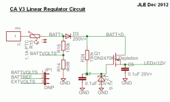
Oh dear, well that was a short lived present! The regulator design is actually setup not just for any N-FET but a much rarer depletion mode mosfet, which are naturally in an ON state and require a negative gate voltage to shut off. This was the trick to get the CA to work below 10V in order to be compatible with 12V pack setups. So if you put in a 4110 or anything similar, you won't have nearly enough voltage coming out of the Drain to run the rest of the circuit. It could work but you'd have to replace the 9.1V zener diode Z1 with something more like 16V.

Here is the schematic for the linear regulator part of the circuit:
CA3 Regulator Schema.gif

To see if the rest of the CA is fine, just apply 12V power directly to where the output of the mosfet would normally be (or to the LED+ pin on the LCD header). If all is well it should power up to the splash screen fine, though it would then enter shutdown mode after that since the measured VBatt would be close to 0V.
 
justin_le said:
Oh dear, well that was a short lived present! The regulator design is actually setup not just for any N-FET but a much rarer depletion mode mosfet, which are naturally in an ON state and require a negative gate voltage to shut off. This was the trick to get the CA to work below 10V in order to be compatible with 12V pack setups. So if you put in a 4110 or anything similar, you won't have nearly enough voltage coming out of the Drain to run the rest of the circuit. It could work but you'd have to replace the 9.1V zener diode Z1 with something more like 16V.
I may well have the right kind of MOSFET in one of my bags or boxes of assorted stuff; just ahve to find time to go thru them and check what they are. If this is something likely to be in PC PSUs or motherboards, laptop internal electronics, assorted SMPSs, I may well have one here.

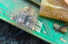
I will have another little problem to fix, though, once I find a FET: when I accdentally damaged the PCB during FET removal, I seem to have removed not only the pad for the gate of the FET, but also the entire trace to the end of R24 and the thru-hole leading to C7 and Z1, and the pad for that end of R2, *and* the actual metallization of the end of R24 itself. The traces I guess are easy enough to fix, being where they are. I'll have to also salvage R24's replacement (should be easy--that ought to be a common value on stuff I have around here).


The regulator itself is a neat circuit, for sure; I am not sure I have seen FETs used this way before--too bad it doesn't work at the higher voltages with the extra drain from the Thun. ;) I guess the majority of systems won't need such a thing, anyway. But I would say it calls for a warning tag on the 5-pin plug itself, so that for those that don't ever RTFM until they smoke something :lol: they will most definitely be warned not to hook something up to that plug that takes power from it unless their max pack voltage is <48V, or they have verified it won't pull more than whatever mA is possible at the higher voltages.

It should save you enough returns to be worth the tagging effort, at least. Even just a dayglo orange sticker with the info printed on it, that wraps around the plug and sticks to itself that must be torn off to use it would be good enough.

Here is the schematic for the linear regulator part of the circuit:


To see if the rest of the CA is fine, just apply 12V power directly to where the output of the mosfet would normally be (or to the LED+ pin on the LCD header). If all is well it should power up to the splash screen fine, though it would then enter shutdown mode after that since the measured VBatt would be close to 0V.


Thank you for that! :)

Yes, it does work if I connect 12V to LED+ at the LCD connector, with ground at the spare GND pin at the edge of the PCB near that. For whatever reason, it doesn't actually shut off, though--it just says "Low V" after the boot screen clears. I haven't re-read the thread (or the new manual/webpages) to see if that's normal for a 12V-powered system.

So since the CA is also designed to run from 12V, then assuming it is safe to do this, I will just:

--wire up a 12V anderson tap from my 12V lighting pack into the CA and run it from that,

--leave the FET out

--connect the traction battery via the normal controller connector

--connect the Thun power wire to the 12V pack instead of to the CA's 5-pin connector (although I could just disconnect the wire off the CA PCB "10v" pad and connect that wire to the 12V CA power instead, I guess).


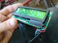
Oh, and I also found (probably already documented in the thread/manual/webpage and I missed it) that on the LCD module, desoldering the pad from R8 to R and resoldering it to W gives me the white light I am used to. :)

Soldering it to both gives a very dim whitish glow in addition to the amber, presumably because the white LEDs normally have a higher voltage drop than the amber, and thus get much less share of the current from R8.


EDIT: nothign to do with the thread, but I note that the
http://ebikes.ca/xmasstats/
map page doesn't have a pin for me on there (unless they're all offset and not anywhere near their actual locations--I suspect this is the case). Also, the page itself is labelled "Torque Arms", not that it matters. :lol:
 
Meant to post this here instead of in the CB2 thread,
http://www.endless-sphere.com/forums/viewtopic.php?p=679061#p679061
but it does work now, after lots of unintentional naps and whatnot I got it wired up.

Possible problem with magnets I'd had on the BB shell before...but I can't tell for sure if that's the problem or not; the sensor appears to send RPM data to the CA, erratically, and sometimes gets torque data, but only when I'm in the calibration screens. When I'm at the regular display screen it doesn't see pedal RPMs except every so often it thinks it sees 15-40RPM. I'll have to make a video.

A definite problem is the throttle--it appears to be pulling down the throttle line all the time, evne though it detects the throttle input voltage correctly, and it *says* it's tracking that output directly, using PassThru mode. I havne't measured the voltage it outputs but if I leave the throttle hooked to the controller's throttle connector, and try to throttle up, it only just barely does so--but the motor does turn at an extremely slow speed (1MPH or less) if i hold it off ground. Presumably this means the CA is trying to ground the throttle line, thru the diode(?) so that it still allows some voltage so the motor spins a little?

Also note that I ahve the voltage range for output setup for 0.89V - 4.20V, same as the throttle actually produces.

Anyway, I'm probably going to see if I can just reset the whole CA and see if that fixes it, as I don't see anything wrong with the wires--nothing shorted or open, and all the solder joints at the pads on the PCB look ok.

Maybe I toasted something else while handling the unit doing the other repairs. Wouldn't surprise me any.


EDIT: oh, and I found a thermal sensor, which reads about 11kohm and dropping at around 55F (temperature in the living room but I was holding it in my hand, so could be reading a lot higher), and drops in resistance as temperature goes up (continuing to hold it in my hand). Hane't hooked it up to the CA yet.


EIDT2: BTW, this particualr bit of setup is extremely unintuitive, and totally confusing; I can't even imagine a reason why it was made this way.
# ThrO->UpRamp and ThrO->DownRamp are nominally 500 and have a range of 000-999. The larger the value the shorter the ramp time (a value of 000 will never ramp). Start simple with 'instant-on/off' operation like that of v2.23 by setting both ramp values to 999.
I do wish it could be changed to the opposite, so that a lower number = shorter ramp time, and the number would best be expressed in microseconds, so that you could have up to essentially a 1 second ramp up, or down to zero time ramp up.
 
pics later, after I go test this thing on the road.

traced down the wires on the throttle thing, and while pulling the controller off so i could open it up and check those, found a note i already knew about but forgot, that the CA wire on this thing is on ebrake, not throttle. :roll: :oops:

Opened it up to fix that, by splicing it into the throttle wire. closed it all up and no go. and now it wouldnt' go even from the regular throttle. great.

opened up again, measured voltages, it's got the right range at the pad, from CA or from throttle connector, so started looking at it with a magnifying glass to see what I screwed up....


After some time i found that while removing the CA wire from ebrake I somehow ripped a trace off the PCB--lifted more than an inch of it away from the board itself, and tore it right in the middle of that. No idea how I did it, as there's no pad there or anything, and I didn't think I'd touched that, but there it is.

managed to lift yet more of the trace trying to scrape copper off the ends so i could solder a wire, and found i could just barely overlap the ends, so i did that instead, and after what felt like hours of trying, managed to touch the solder, iron, and traces together all at once without knocking them apart, and that fixed the problem.

So now it at least runs from either CA or throttle.


one problem i see sometimes is that off ground it doesn't regulat speed properly (set to 20MPH, 2000W, 80A all as limits) as it goes way overspeed at first, up to 23mph, before it will even attempt to regulate downward. I used a glove as a load, maybe 20-30W, no change. When it does finally regulate, it cuts down to 19.9-20.1 just fine, but if I'm holding WOT and letting it freewheel, it goes in heavy bursts of power as soon as it lets go of regulation once speed dips down far enough , instead of trying to constantly regulate speed. Will see how it acts on-road, but what I expected (and will have to poke at the settings to see if it is just set wrong) is a regulation of throttle output to try to keep that speed, rather than what it "feels" like, as if it were cutting throttle entirely once it hits the speed.

Also, sometimes it randomly seems to still see several hundred watts of power usage even when i let go of throttle and let the wheel spin down. Somteims it goes back to zero on it's own, and sometimes I have to powercycle it. I wiggled connections and found no change, so I dunno on this yet.


No luck on the Thun sensor yet--today it won't even detect that it's doing anything at all, so I suspect a broken wire or bad crimp in my extension cable.

Oh, I forgot--last night i did find that it only sees the thun in reverse motion, so it is definitely backwards in there, but I don't know any way to fix that--this BB really is threaded backwards I guess. That's ok as I didn't really plan to use this on CrazyBike2 anyway, but it would have been fun to test it out on there.


Maybe I'll install a CA connector on the Fusin Test Bike's Fusin controller, and see how it works to control that system, if I get time, eventually. (i am planning to take the second week of January off work for "vacation", though it will actually just be to finish stuff around here I can't seem to get done under normal time).
 
14-mile test ride went ok, but it's cold out there.

I don't have the controller shunt calibrated properly, but it seems to be close. Most of the time it is within a couple dozen watts of the other CA that uses it's own shunt. Sometimes, though, it goes up to a kilowatt or two off (either way) until I touch the connector at the CA-to-extension cable to the controller. When I got home I tried to find a problem in it but I can't. Maybe a wire is broken inside it's insulation, but if so I can't find it.


I tried different throttle modes out, but the only usable one (at least, until I figure out the settings?) is Pass-thru. All of the others either work for a moment and cut out, before I even get started, and then after several seconds, *after* I already let go of the throttle and am trying to figure out why it isn't working, it suddenly tries to start up again, just for a moment, with a large surge of power (about 2KW according to the other CA). The first time was pretty spooky, because I most certainly wasn't expecting it.


As I didnt have any of he settings explanations with me, I stopped trying the different throttle modes and just left it on PassThru mode.


I also found an intermittent issue: if I max out throttle, it cuts out--but if I let it off just a teeny bit, it starts up again. When exploring the settings, I find that if the "throttle in" range is set below the actual voltages it can put out, it will stop "reading" the throttle when the throttle voltage goes above that. So if I have the in range at 0.89V to 4.20V, and the throttle goes up to 4.21V, then as soon as it hits that 4.21V, the CA will output nothing for the throttle. :/ Simple to fix, but annoying, as I thought I already had it set right.


I ahd another setting that "changed itself" at some point, but I forget what it was. It is possible that setting was auto-altered by changing some other setting, but since Ic nat' remembe what it was it's hard to check the manual for that. :(


I had to disable the speed limit and power limit because whenever either is reached, power is completely cut for up to several seconds, which is dangerous in traffic. I'm hoping there is a setting to fix this, because this type of limiting is worse than useless; it's the same problem I have iwth the Fusin kit's "analyst" display and it's speed limiting.

I'm pretty sure there must be a setting for it, because I seem to recall the CA is supposed to roll back throttle a little at a time as limits are approached, rather than just cut off like that.

I'm off to re-read the "manual"
http://www.endless-sphere.com/forums/viewtopic.php?p=571345#p571345
again. :(
 
anybody still have the schematic for v2 smallscreen ca power section?

spent an hour scouring es & google with no luck, just v3. :(
(edit: spent a couple more hours searching with no better luck; emailed info@ebikes.ca to see if they'll provide the schematic for that section)


my surprise, i ran across the two old ca small screen units in a box of unrelated stuff, some smoke damaged, some not. id thought these were destroyed in the april 2013 housefire, having been last seen in the projects boxes in the bedroom the fire started in. guess not, and someone helping with cleanup mustve put them in this box of assoted electronics bits.

i fixed them partially way back, one documented above, but couldnt do the rest.

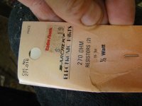
today i fixed the rest of undocumented one that was not burned (maybe from bikefanatic?), it had no pads for r9 on lcd pcb, so i seriesed 2 ancient 270 ohm 1/2 watts and ran them from unused anode pad to led+ input pin, now it works afaict.


not so lucky on one this thread started for.

r8 &9 both heat destoyrd and broken pads ripped off so i fixed r9 like above w even older 560 ohm 1/2 watt and r8 from kathode pad to led- pin w 1w 160 ohm that is probably older than i am.

but no go. got batt + 53v at both led+ and led- and topof q1 case, so theres prob no ground in circuit to let it work. stiill tracing pcb out comparing to now-working unit, but no joy yet, is hard cuz of conformal coat and shaky hands.


edit
q1 may be toast again, diode test meter black on case tab reads 471 from case tab to z1 shared lead,and infinite from case tab to c10 shred lead.

but same on working unit is reversed w 471 from case tba to c10 and inf to z1
 
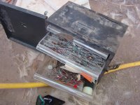
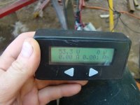
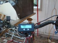
forgot the pics. first the one i got fixed, and the box of ancient parts used to fix it, plus it on the sb cruiser now mounted on teh steering tiller tube.
dsc06226t.jpg
dsc0622t.jpg
dsc06228t.jpg
View attachment 5
dsc06231t.jpg
dsc06232t.jpg
dsc06237t.jpg

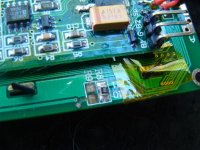
then the one with fried traces that this thread started with;
dsc06233at.jpg
dsc06234at.jpg
 
No reply from Grin since Justin asked which version PCB it was (rev9); I've had no more time since then to try working on it anyway, so doesn't really matter yet, but I was thinking about it today when working on getting stuff installed into the new computer, when I realized I would rather be taking the CA PCB apart and peeling stuff back layer by layer and finding what goes where and wiring up my own on a breadboard, than working on the computer. :lol:
 
Got a reply with the PCB layout info, so I can trace out the traces and see what is and isn't connected where it should be (or is connected where it shouldn't be), to determine if it is or is not a component failure instead.

(as damaged as the board already is, I don't want to pull parts off to test them unless I absolutely have to, because it's nearly certain that anything I remove will then have to be glued back on and hand-wired to the rest of teh board after that).
 
Hello, Justin and other EBikers.

Large CA-2.23. PCB: CA2.Rev11

Q1- P/N (IXTY08N50D2) ?
U3 - P/N (XC6219xxxxx) ?
Q3 - P/N (Marking Code 302p8) ?
U1- its MCP6002 or AD8539 ?

Best Regards,

P.S. I sent three latters to techsupport (info@ebikes.ca) from 6104139@bk.ru
 
Hello, Justin and other EBikers.

Large CA-2.23. PCB: CA2.Rev11

Q1- P/N (IXTY08N50D2) ?
U3 - P/N (XC6219xxxxx) ?
Q3 - P/N (Marking Code 302p8) ?
U1- its MCP6002 or AD8539 ?

Best Regards,

P.S. I sent three latters to techsupport (info@ebikes.ca) from 6104139@bk.ru
 
I tried to get the p/n's for the above request off my CA but I can't read them; my eyes just arent' good enough anymore. If I can find my magnifying-camera setup, I'll try again and post them.


I started trying to trace out the PCB from part to part, but no luck yet; each trace I try seems to show good connectivity, though it shouldn't based on the actual behavior. I'm thinking it's a layer-via issue, perhaps. :?

Have to get back to it later.


I've also got to go back to the other SS CA, and find out why it reads so far off, regardless of which shunt is used and what shunt value it's set to (even for shunts that work fine with the LS CA). Maybe I'll have to recalibrate the CA; have to see if the procedure is on the Grin Tech site or CA manual (it's not normally something that ever has to be done).
 
Back
Top